Neje N30820 + 3018 GRBL 1.1f Questions

Hey,

I recently bought a Neje N30820 30W laser. I connected it to my cheap 3018 CNC (had to swith TTL and GND on the board connector) and started reading a lot. The 3018 I have comes with the Woodpecker CAMXTOOL V3.4 board. As far as I can tell, this board has a ATMega 328, so it’s 8 bit.

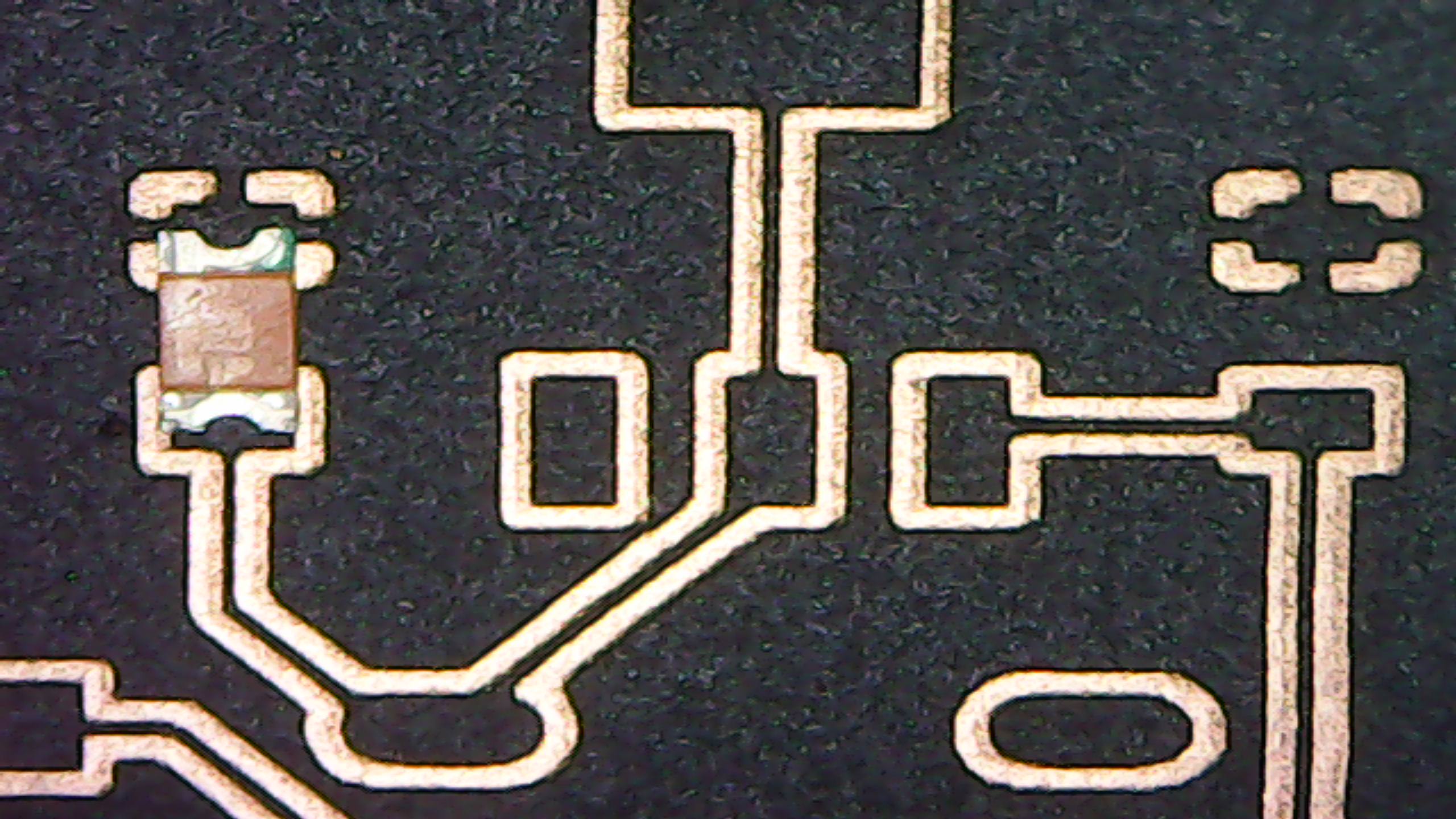
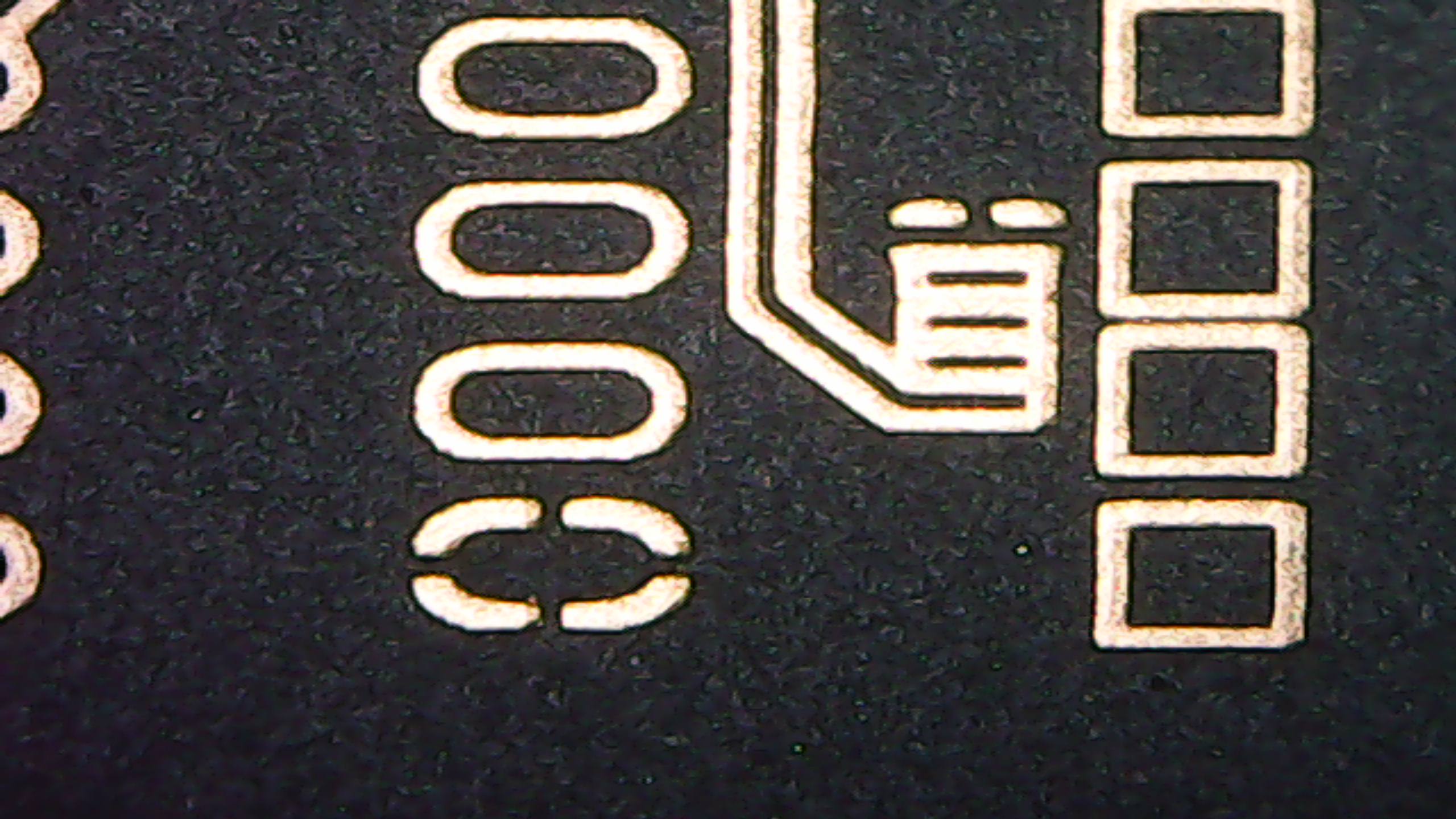
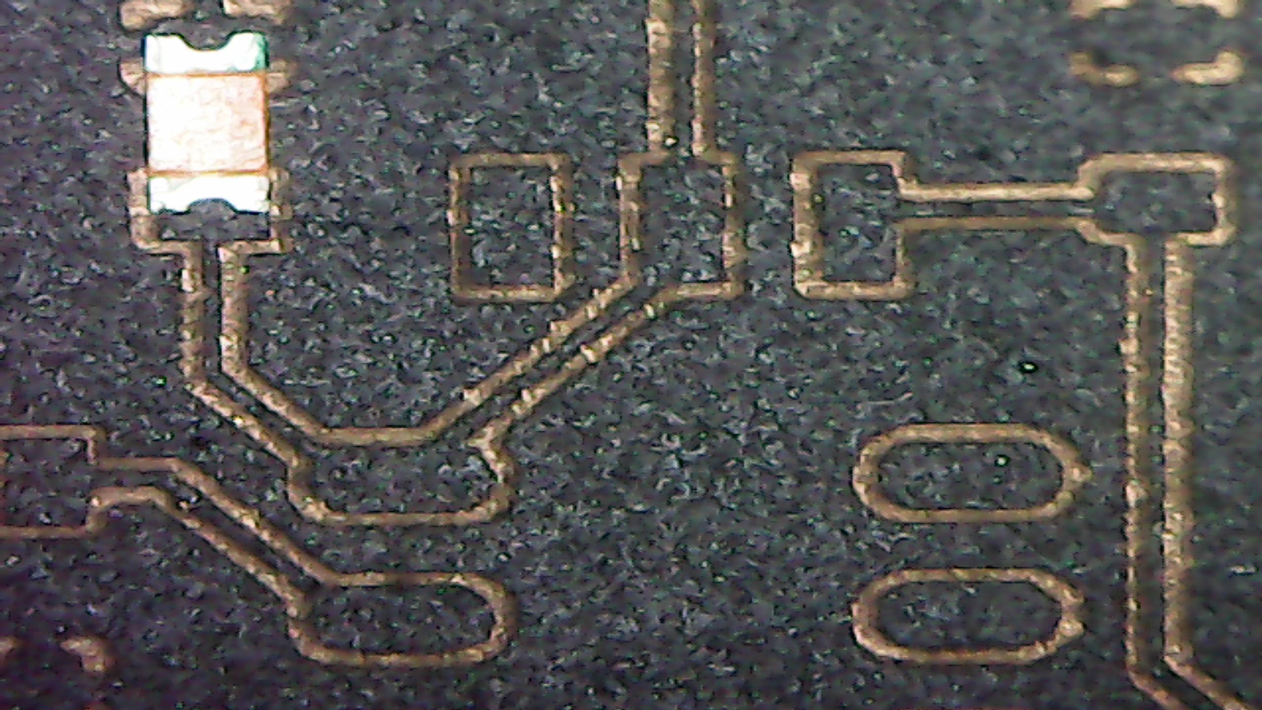
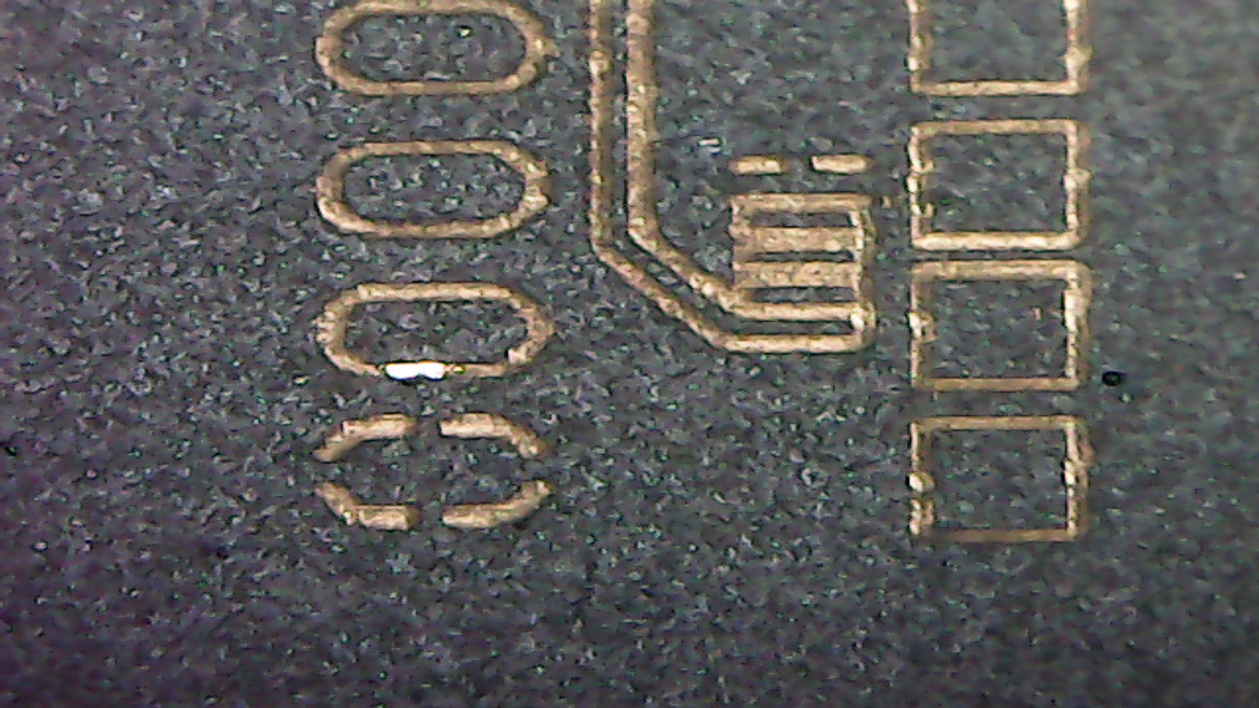
I already tried it out, but my results were not so good. The main purpose for me is creating PCBs by the “spray-paint and etch” method. During my tests and during reading all kinds of documents (I already checked the “Configuring a 3018 CNC…” tutorial here) and came across a few questions and I hope someone can help me out here.

  1. According to the configuration tutorial mentioned above, 8bit boards can set the power only from 0-255, but when reading the settings with “$$” it shows the value 1000 for $30. So how would I have to set the power now? Would setting “M3 S200” be 20% or ~80% ?

  2. What would be good values for etching a spray-painted PCB? I have absolutely no experience and would love to have some starter values for power % and speed.

  3. Since I’m currently on Linux, what would be the best way to create a gcode file from a eagle layout? So far, I’m exporting the schematics to image, open that with inkscape, and the export it using the LaserPecker extension.

Thanks in advance.

  1. the parameter $30=1000 is correct and in Light Burn you must put the power in percentage 0.1% to 100%. Internally the gcode is generated from 1 to 1000, where 1000=100% (i.e. /10)
  2. save as pdf and import in LightBurn or burn as image (jpg)

PWM is very simple, don’t over complicate this. It is based on a ‘period’ (1/frequency) during that period the PWM signal is high (laser on) for the specified percentage of time. This gives the illusion of power control.

If the device generating the PWM is an 8 bit PWM generation that limits the control to only 256 steps from 0 to 255. If the device is 16 bits the resolution is now 65536 steps. Finer degree of power control.

Lightburn assumes 0 to 1000, so if your upper/lower limit ($30/$31) are set properly then you will get a 50% PWM output for 50% power setting. This was in the common grbl setup procedures supplied by Lightburn. Did you go through that?

Generally what you find is that BOTH the generating software and the firmware on the controller have to agree on what $30 is for a proper function of the PWM.

Set it to 1000 as recommended by Lightburn.

If $30 is set to 1000 then the PWM frequency is 200/1000 = 0.2 or 20% PWM. You can see where the problem lies if $30 is set to 255…

No one can give you values. Maybe something to start at, but I make my PCB’s on the CNC3018, so I can drill holes that don’t look like a drunk did it…and the components actually fit.

Are you going to use regular paint?
Make sure whatever you use for an etch mask is safe to lase.

I too use Linux (Ubuntu 20.something) and followed the work flow you described for PCBs. I think I’d try a different tack rather than running it through Inkscape. I might try exporting the image from Eagle or even a screenshot of the board and using Lightburn to ‘trace image’ and create areas you can ‘fill’. I think it’s more along the flow path that Lightburn would work well with.

If generating in Inkscape, what diameter of ‘tool’ are you going to tell Inkscape you are using? I’m sure that will be a lot of passes. I think your workflow will have to be different after the Eagle design is complete.

Hopefully this makes sense.

If I have time, I’ll try to trace one of my simple boards and see how it works…

Good luck, take care and have fun :slight_smile:

:smiley_cat:

Thanks for the answers. I haven’t found much time yet, but I tried a few settings in another software to generate the gcode (I only have lightburn trial installed recently and had no time to play around with it yet).
Etching generally works OK so far using 40% power and 400mm/min but very small parts (like the legs for a SOIC-16 device) are getting even a bit smaller. Maybe my laser is still not perfectly focused, but it looks pretty good to me.
I will need to make a lot more tests I guess. As for the spray-paint, it’s just regular matte black. Of course you need good ventilation when running the job.

Have you ramp tested the laser to see the best point of focus?

:smiley_cat:

Hey,

yes, I used the “ramp” method to focus the laser. I had a little time today, so I tested with LightBurn, as well as with LaserGRBL. Both times the same settings (20% power, 100mm/min). In LaserGRBL I was able to set the number of lines per mm to 20. I wasn’t able to find that setting in LightBurn, but as I said, I currently only have the Trial.
While LaserGRBL created a pretty clean result, very small details (like the solder points for a micro usb connector) and the traces are not as wide as in the image. This can be a problem depending on the wattage running through those parts.
LightBurn did not remove that much, but the result itself was way less clean. It looks like there is still some spray-paint left on the copper. But the traces are better, almost still original size.
I attached a few pictures for a better comparison. Since I only have a very cheap microscope, the quality is not the best, but it should be good enough to see what I mean. The SMD LED on the pics is a 1206 size.


Those two are from LaserGRBL. The trace under the LED should be around 33% of the pad width, but it’s way less. The second picture shows the connection for the micro usb connector. The smalles one is only about 0.1mm thick :confused:


Those are from LightBurn. You can see under the LED the trace is better, but still not perfect. Same goes for the usb connector. The whole result looks like there is still paint left.

Maybe I just want to much, and it’s not possible to get good enough results with the laser I use, I have no idea to be honest.

It’s in the cut layer, double click on the layer in the ‘layers’ tab.

I never tried my laser on PCBs because all of mine need holes, the laser can’t do.

There are other here that do this, so hang in there and we’ll see what ‘develops’. :slight_smile:

:smiley_cat:

Thanks, I’ll try with that setting the next time. Maybe someone who also creates SMD PCBs can also shed some light into this.