I can’t get going with my new camera, LightBurn 5mp-120. Running 1.3.0.1 on a MacBook Pro. The camera is mounted solidly over the center of my 5W Nasum A5 and shows up in the camera window, but 90% rotated. I tried the calibration capture and can’t get a single valid capture on the dot pattern. The range is about 27 to 9000. So, I used the LightBurn 5MP-120 preset. When I next tried the alignment, using the default values, the Frame button frames the entire scope of my machine, not the white paper on which the pattern should burn. I’ve tried multiple times. The Camera Window capture is still 90 degrees out and I can’t get the frame to find my blank paper.
Also, when it asks for material thickness, is that in mm? Cardboard and paper would be about 3mm?
I’m gonna check previous topics to see what might help, and if I figure it out, I’ll report back to this topic.
I got a good calibration and alignment, finally. Up to a point. My Overlay shows sideways, or 90 degrees rotated to the right. This makes it impossible to use the camera to line up designs, since the workspace is “right side up”. When I drag a design into the workspace and update the overlay, it appears a quarter turn out of phase in the overlay shot.
So, I’ve gotta figure out how to correct the sideways overlay. Before you ask, yes, I did the alignment correctly, marking the centers in 1234 order. That didn’t change a thing in the overlay. When I cut the alignment template, #1 was in the upper left of the laser work space, as it should be. I had to use a large sheet of paper, as I could find no way to shrink the template to fit an 8 1//2 x 11 sheet. The final template covered most of the 410mm x 400mm laser bed.
Could it be something in the Mac software affecting the camera orientation?
Not the most frustrating thing in my 73 years, but maybe in the top 10%.
Also, there is no inches or mm specified in the material thickness box. I’m guessing it’s mm, as the sentence before that in the dialog box mentions 200mm x 200mm. That’s why I couldn’t figure out what to put in that box.
Material thickness correlates to the units set in the Numeric Edits Toolbar from what I remember.
If you had done the target alignment in sequential 1-4 order that should have resolved this so that’s odd.
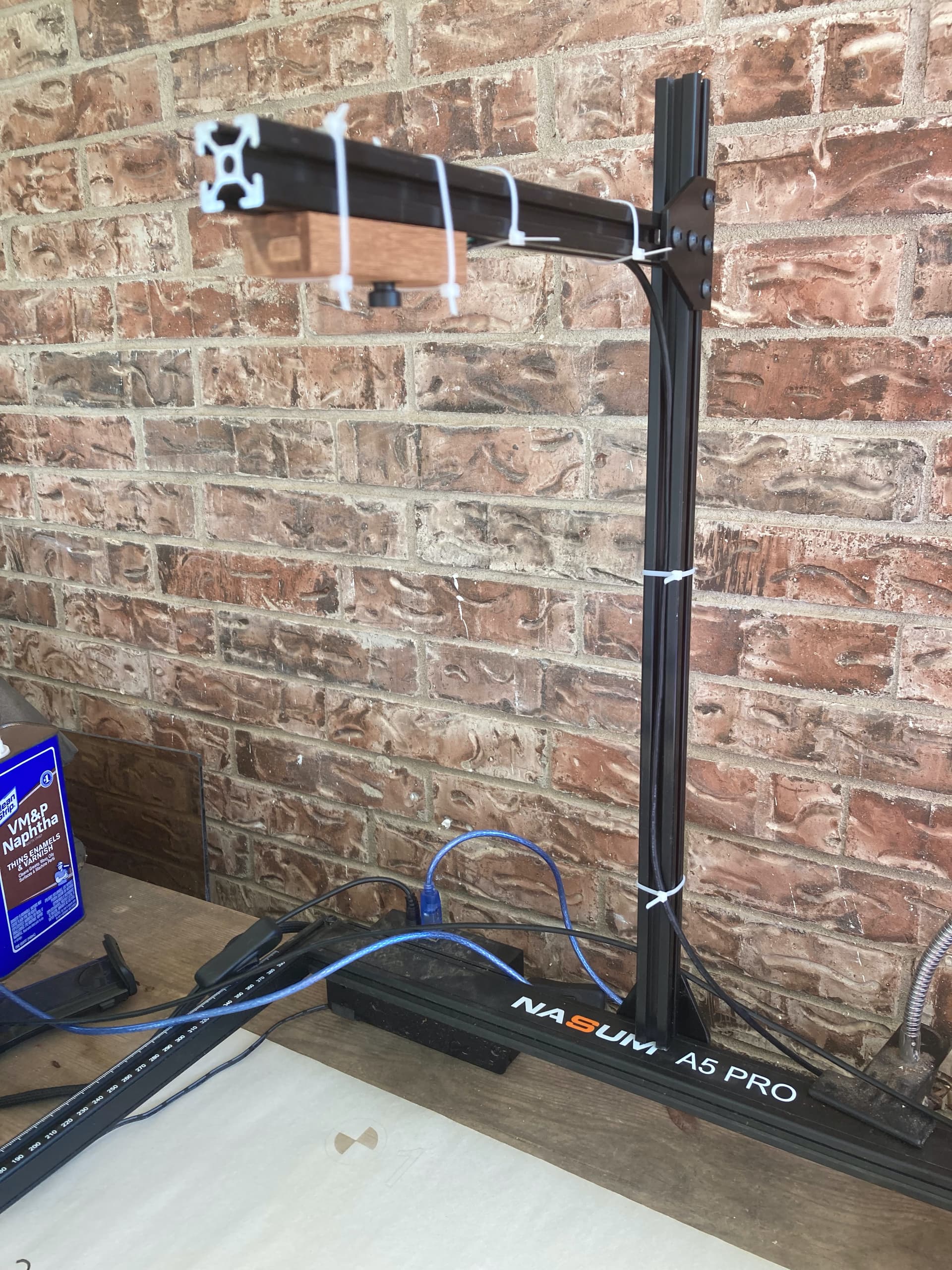
Can you take a photo showing the camera relative to the laser?
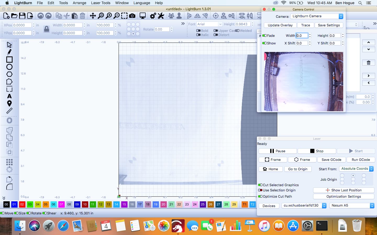
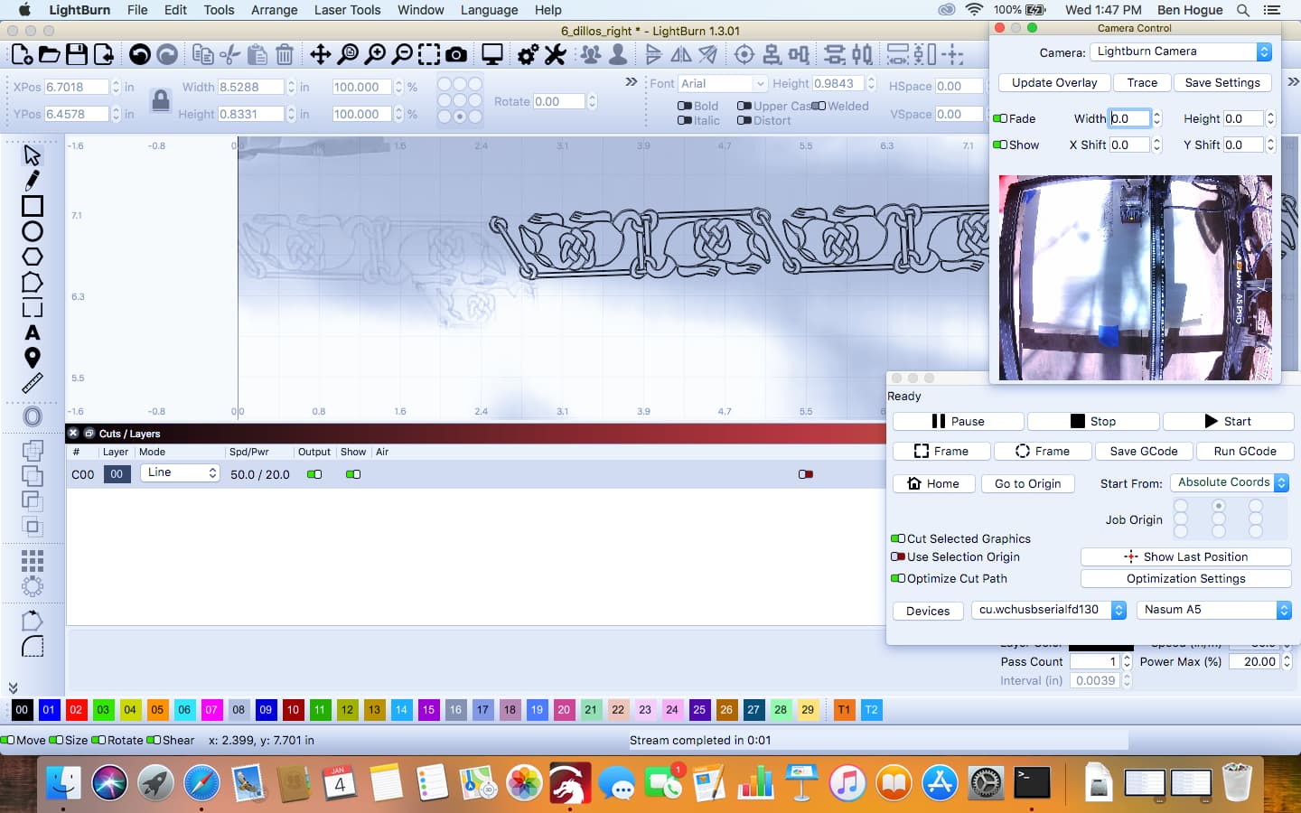
Also, can you take a screenshot of LightBurn with the Camera Control window open and an overlay updated?
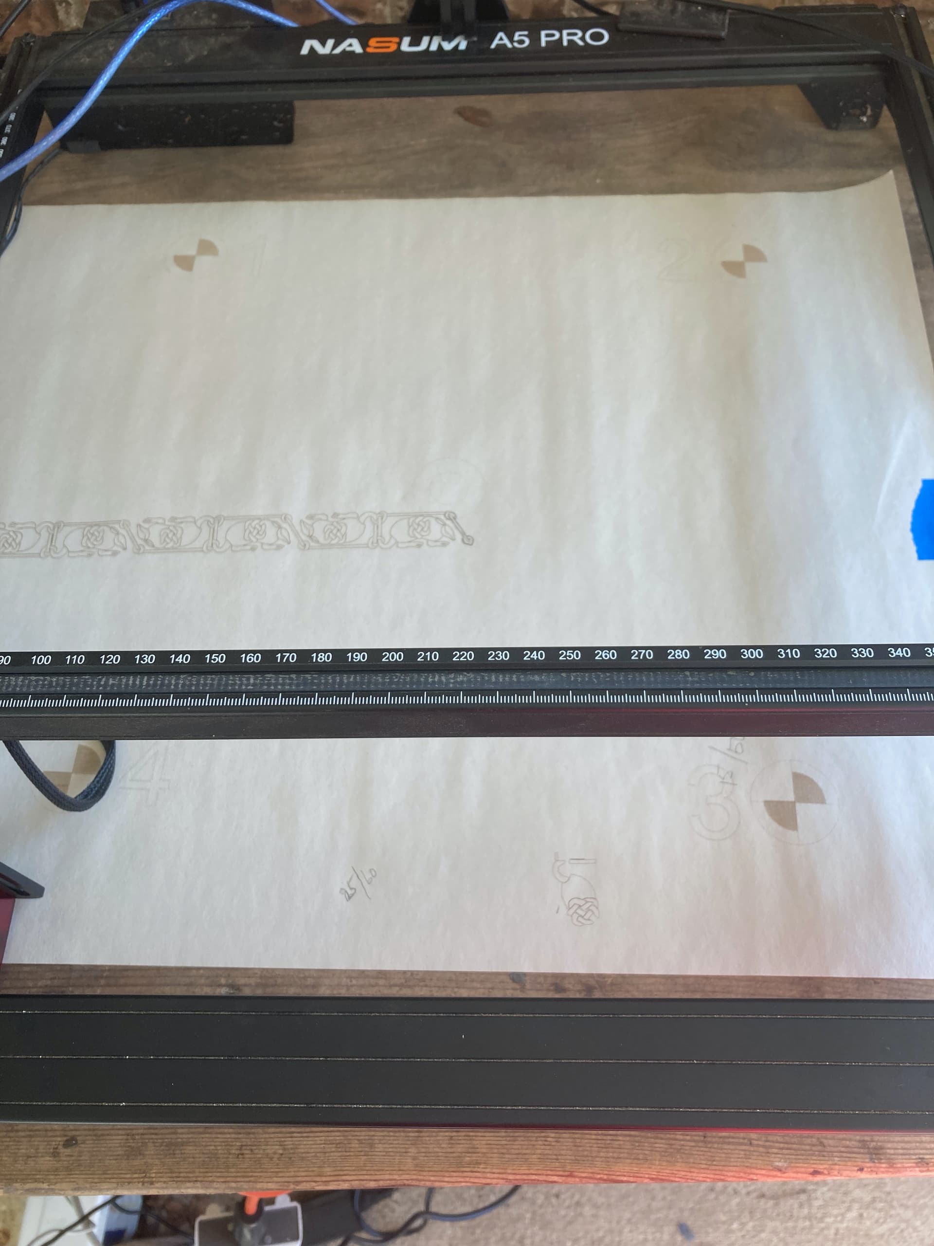
Here are shots of the camera, Nasum bed, and screenshot of LightBurn. I checked for a MacOS camera control, and there is none. I also can’t find anything in LightBurn that allows me to control camera picture orientation. Could it be something in this particular camera that got mounted wrong? Would mounting the camera sideways likely make a difference? Mine is mounted in the same orientation I’ve seen on other laser cutters.
To repeat, the alignment was done according to instructions. The targets printed out starting with #1 at the top left, and I double-clicked them in 1234 order.
However, you have a lot of other issues going on, primarily distortion and likely alignment.
I’ve previously mounted a camera this way without issue. Note that the orientation of the live image in Camera Control window will not necessarily match the overlay.
The overlay should match the orientation of the bed.
Did you use the pre-canned lens calibration or did you do a custom lens calibration? If custom, did you use fisheye or standard? You’re seeing far too much distortion for this to work properly. When you did alignment, were you seeing a distorted or corrected image?
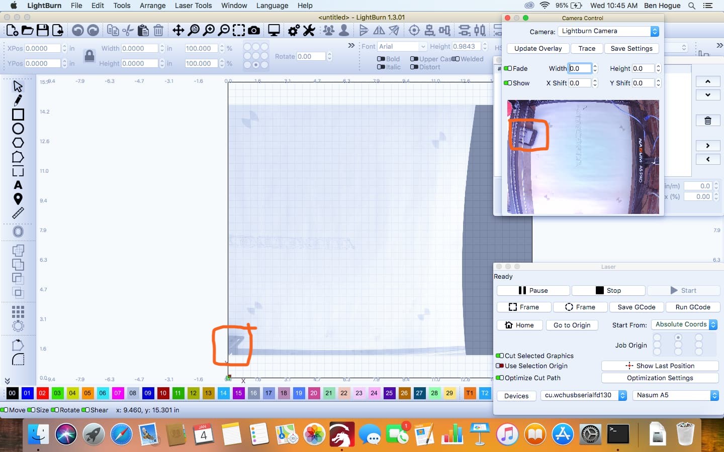
You’re not seeing what I see. Zoom in and look at the light image I burned on the paper on the bed. It’s horizontal. Now look at what it looks like in the Camera Control image: vertical. The corners you marked tell the story. One is bottom left, the other is top left, or 90 degrees different.
What I want to do is cut a design on a leather strap that is too long to do in one file. So, I have 2 files and I plan to join them using the camera for registration. Right now, the version in the Camera Control window is sideways, which is disconcerting. When I line things up using the burned image and the second file, the registration is completely off. See the attachment, where I started the second burn, and it’s below and to the left of where it should be.
I realize this is evidence of bad alignment, and I will re-do that. I also realize I can correct small irregularities in alignment using the X and Y adjustments in the Camera Control window, however currently the second image now actually burns several centimeters off in both X and Y, and I have to scale the second image down to fit. I almost think I could get much closer without the camera, and in fact I’ve gotten pretty close using “current position” rather than absolute coordinates.
I’d be willing to work on it some more if I could get the Camera Control picture horizontal to match the work space. Otherwise, I may have to abandon the whole camera idea.
I checked and have not found a Mac camera app that might let me adjust the orientation problem. Nothing native to High Sierra, and I haven’t had time to look at everything on the App Store.
I thought I was clear on this but may not have come across. This is expected. Your Camera Control image will be vertical. However, when you capture the overlay the image will rotate to match your bed.
So as long as the overlay is correct this is how it will work.
Are you splitting a single shape across two areas? Or is there whitespace between burns? If the former I’d suggest you use a jig or print & cut rather than trying to do this with the camera. If the latter then the camera may be good enough to get you what you need.
This is due to the fundamental issues with lens calibration and alignment. I suggest you correct those issues first before attempting this.
As you say, I’d suggest not relying on this for anything more than a few millimeters of adjustment.
I’m not aware of any way to rotate the camera view in Camera Control window but I’m curious why that’s a problem. If this is somehow a showstopper then perhaps rotate the camera on the mount.
Well, that’s all very disappointing. For one thing, every youtube video I’ve seen on LightBurn and cameras shows a horizontal shot in the Camera Control window. Also, they all led me to understand that registration accuracy with a camera of .5 mm was possible and likely. But then, they also said calibration and alignment were easy, which was not the case for me.
As for my current and recent projects, I’m doing belts and guitar straps on leather with continuous patterns that are too long for the capacity of my machine. In one case, I was able to split the pattern at a place where there was only one horizontal line, and I did that by using a straight edge and carefully aligning in Current Position (not absolute coord) mode. However, the current project must be aligned by overlapping a repeated part of the design, which is much harder to register.
I wonder if I can get Lightburn to take a return on the camera?
If that’s important to you then mount the camera horizontally to the X-axis. The value in mounting it vertically is to potentially maximize camera resolution in case you have a taller machine than wide. Yours is close to square so may be non-issue.
You may be able to get close to that under ideal conditions but you’re going to have to very tightly tune the lens calibration and alignment processes. You also have to keep in mind that placement alignment will only work at one focal distance. It doesn’t look like you have a vertically movable bed which means material height will affect distance to lens. This will absolutely affect placement accuracy.