New depth independent position cross pointer project

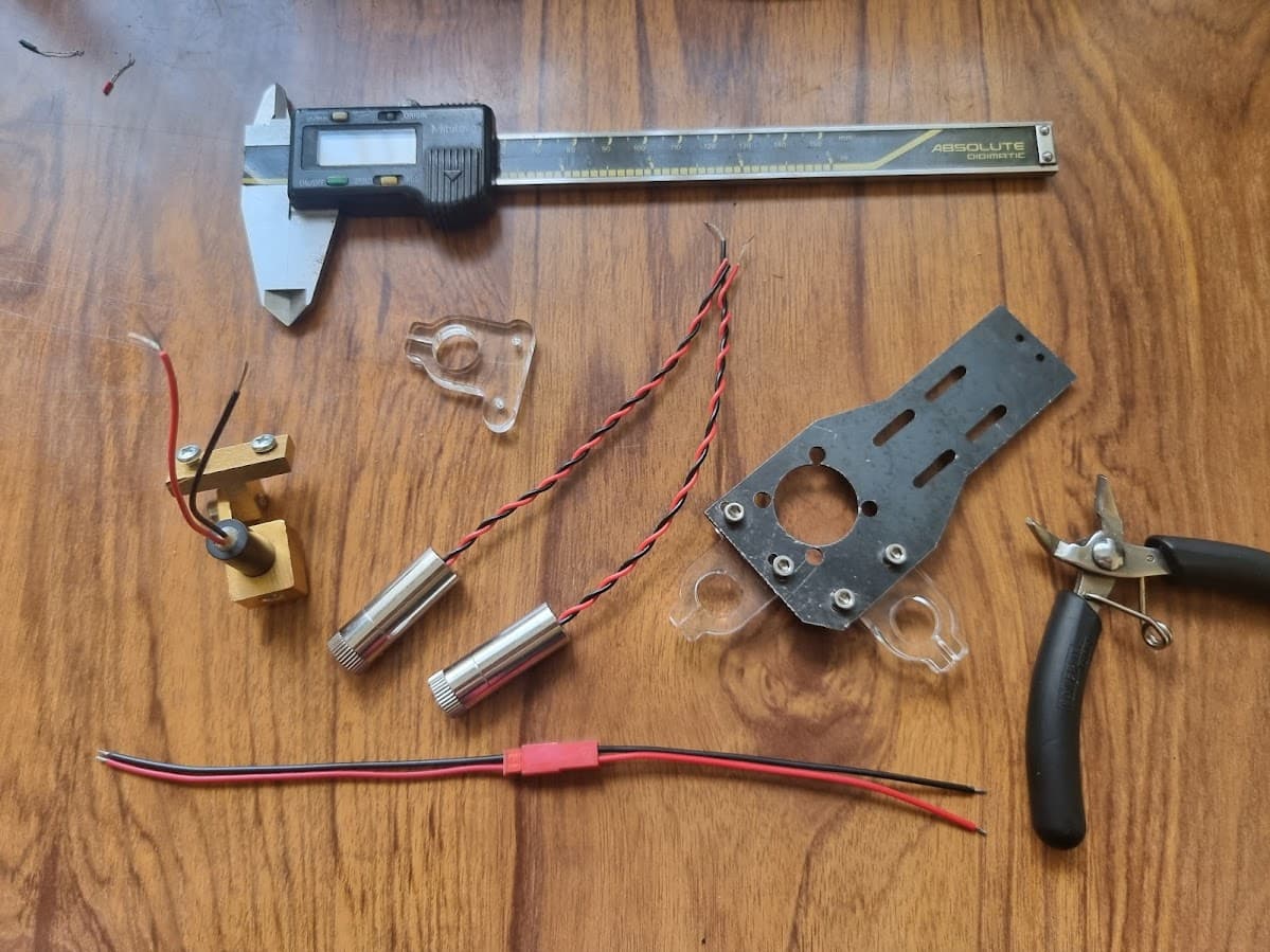
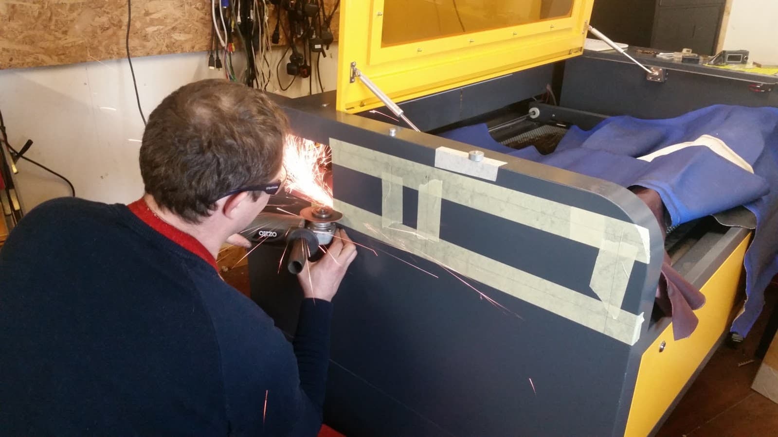
Today’s engineering day. Got fed up with single point position marker, which wasn’t functional to begin with due to rubbish wiring breaking in the chain of X axis (within 200 hours of machine operation). Decided its finally time to make a proper depth independent cross marker for my laser cutter. Lasers for my laser… Also upgrading wiring from pvc coated 10strand to silicone insulated 50strand flex wiring (i use it in my drone builds for low power distribution).

Needed another holder like the one that came with the machine (yellow part), but apparently its as rare as magic unicorn poop and no one, not even china, sell them. So, have to prototype and cobble something together myself.

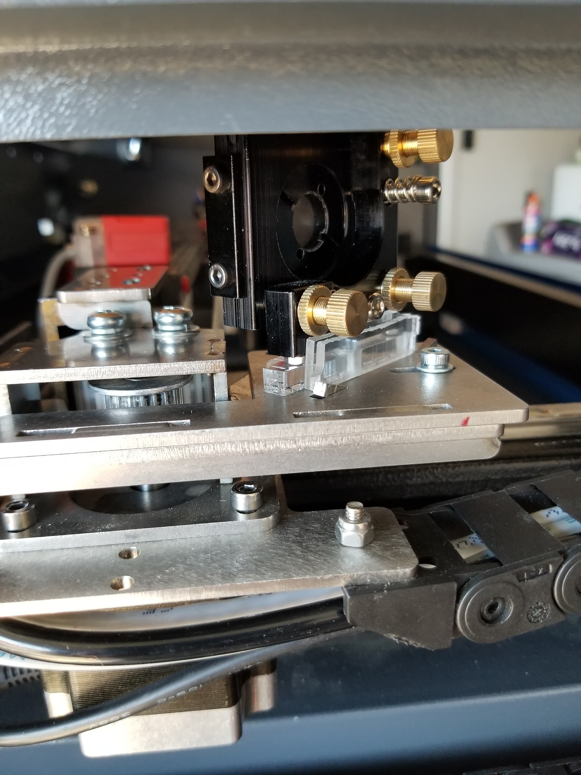
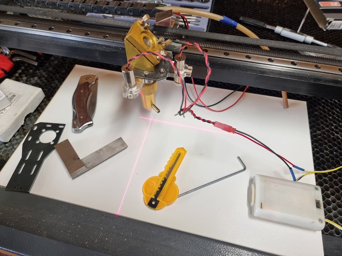
Head mounting plate is also custom made by me (2mm steel) as original was made of 1.6mm chinese aluminium cheese. Added holes on the front for second line pointer to form cross mark, which is independent of bed Z position.

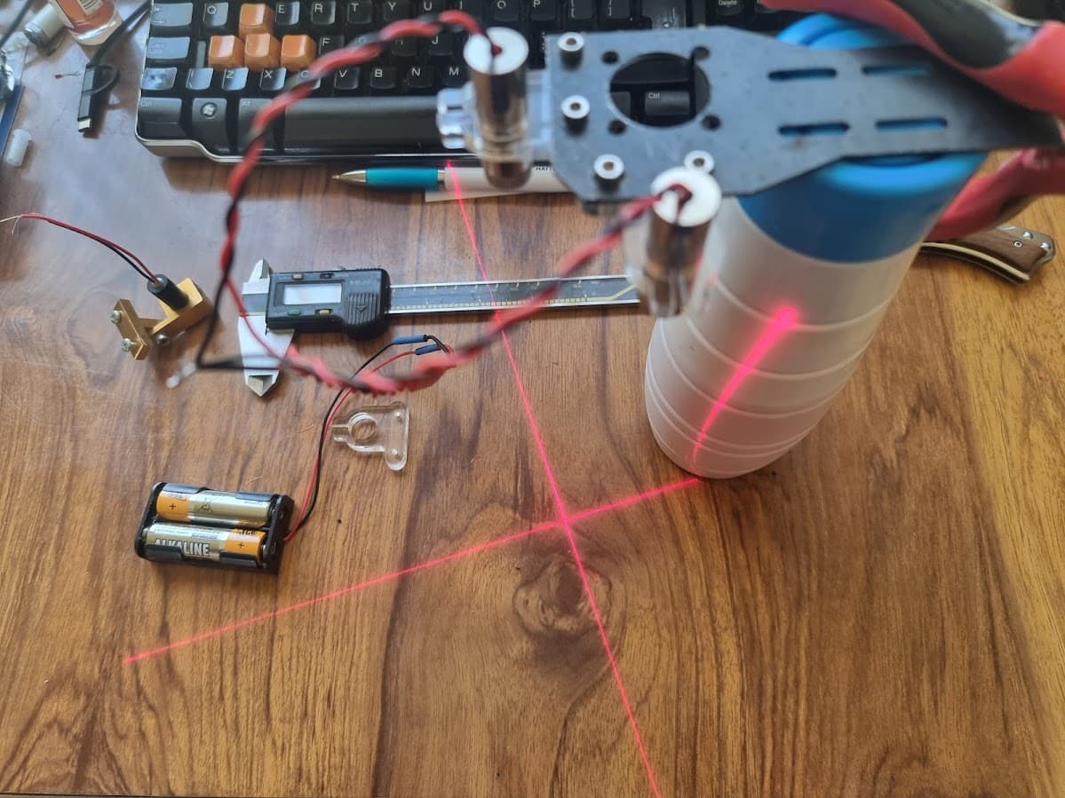
The pic with pointers powered up is just a test - alignment/focus and centering can only be done after i install the lot on actual head plate and laser draw an alignment pattern, so for now its just to see if it powers up. Using spare plate just to see how things fit.

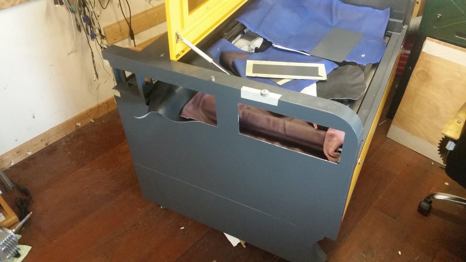
If things work out the way i see them in my head i’ll have a bed wide material alignment tool, as honeycomb on my machine is not fixed so absolute positioning for registration is not really possible. Plus, being height independent it wouldn’t need head to be “in correct focus” for actual indicated position to be correct.

Amount of mods in my terribly “engineered” machine is increasing…

Things done so far:

  • Replaced bed mounting brackets (bent out of the box, thin cheese metal, wrong sized holes, incorrect number of holes),
  • Head mounting plate, was too thin and wobbly (1.6mm alu to 2mm steel, added holes for second pointer, for this project specifically.),
  • Replaced X motor (nema17, overheating, unknown spec, not driver related),
  • Modded incorrectly drilled X motor mounting plate, - Replaced wobbly linear bearing block on X,
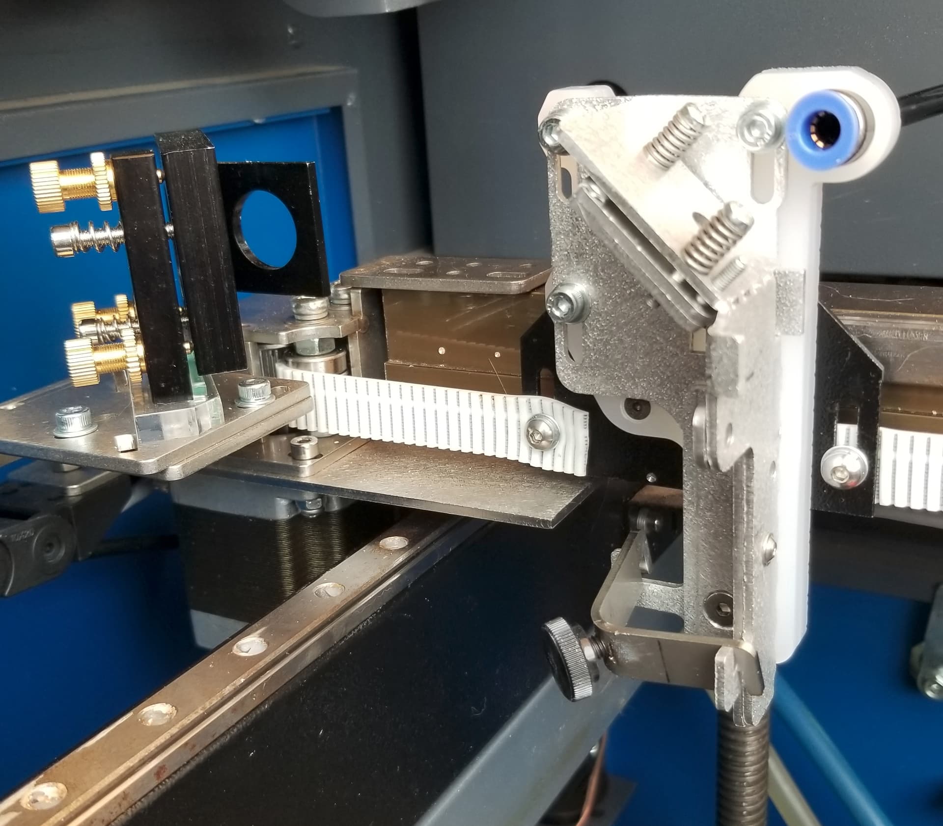
  • Reworked “tensioner forks” (if you can call them that) to take 4mm bolt as axle for proper metal idlers, originally plastic with ONE bearing, wobbling all over the place on a needle thin axle,
  • Replaced MXL belt to GT2 belts, due to motor replacement which had MXL gear pressed on, needed to get available GT2 pulley onto bare motor shaft, hence belt change,
  • Replaced spiral cut motor to drive shaft couplers on Y to proper spider couplers.
  • Replaced HV PSU, it blew flybacks within 50 hours of operation (ZYE MYJG100W),
  • Added digital power meter as machine came with NO METER at all. If i didn’t study my thing i would have blown the tube in 2 months (80W tube, 100W HW-PSU). To this day my 100% (22mA, being safe) power is actually 42% in Lightburn.

Things still to do:

  • Replace dumb ac motor on Z to stepper, problem being Z is chain driven, not belt, looking for a chain sprocket to fit shaft of nema23 (6.35mm ID?),
  • Replace nema17 to nema23 on Y, preferably with reduction, which will be extra tricky because of stupid “engineering”, no standard widely available belt reductors fit the space available…
  • Replace mirror no1 holder, as the current one is the most atrocious K40 type.
  • Replace some other bits and pieces…

Thinking back i should have just added another grand and gotten myself a better machine…

1 Like

This type of led setup seemed a real popular addition to a lot of K40s I’ve seen. How do you align the leds beams to be perpendicular to the lens axes?


I did my best to get mass off the X axis…

IMHO, you need to turn down your lps as you are probably driving the tube a bit hard.


I think the engineering on these machines are pretty smart, they can’t keep them in stock. I bought one, you bought one… they went to the bank… can’t read any English complaints…


What kind of mA meter did you purchase? I have both the digital one on the supply and an analog one on the console along with an hv meter…

The digital one bounces all over the place when it’s running anything and is at best difficult to use.


Mine came with a honeycomb bed, haven’t found a good use for it yet. Replaced with rolled steel sheet.

I’ve also replace the head and some of the other X axes parts.

I found my Z table ‘wobbles’ because of the long screws being bowed. I also don’t have a z motor… :frowning:

I think a few photos of your machine would be nice…

:smile_cat:

My machine is an overgrown K40 (upon later research, sadly). I’ve seen these dual line setups, but most of them only for head position, not aligned to line perfectly with X and Y axes AS WELL as crossing over at head position. I’m planning to draw big cross on a piece of mdf and align on existing mark to be both X/Y and position accurate. The pointer plates and head mounting plate allow me to move pointers to a degree to allow for that.

My X is light as is, as gantry beam is the skinny one at 40x20mm, small chain, and yellow small head. I engrave at 400mmps, but only limit here is small direct drive nema17. If i remember correctly whole gantry/bearing/head weight is under 400g.

According to digital meter i fit to ZYE MYJG100W i never go over 22mA (while cutting, no meter jumping), plasma colour is nice and pink at 22mA.

Mine came with subframe to fit blades, but no blades, only honeycomb. However i got sheet of stainless cut to fit over it (screwed down to subframe), sheet is full of holes to keep extraction pulling through it. Knowing how honeycombs bow under their own weight in the middle, i placed small machined blocks on the table (around 20 blocks, inside hcomb frame area) to lift the comb off the steel, which keeps hcomb level and allows for extraction.

My Z came with ac motor thats operated by 2 buttons on a side of the case, but its WAY slow so i cant see wobble if there is any, but judging by quality of the screws i got in there i wouldn’t be surprised if it did wobble. Cant get proper ballscrews with belt drive for it as not a standard construction.

Machine looks like this:


Looks great… I like seeing other peoples machines and the mods they’ve made.

Thought it was similar to this.

Mine was a standard China Blue 50 watt (measures 44, 880mm length).

There is no drag chain or leds… minimum weight. It will go fast (too fast) and I have substantially increased the acceleration that’s possible.


If 22mA is max and you get that at 47% what do you think the tube is drawing when it’s in the ‘on’ state?

It could be easily argued that the 22mA reading is really only 47% of the actual current.

Think about how the laser functions during a single pwm cycle. When the pwm goes high it lases. Is it lasing at 47%? No. When it’s on, it’s drawing as much current as the lps will allow.

If it’s 47% @ 22mA, it’s probably closer to the 44mA of available current during the on time. As 47% would be less than 1/2, I’d estimate at least double.

Another issue with an lps designed for a higher power tube, it responds faster, but has more available current.

That’s why, IMHO, I suggest you limit it’s current capacity…


I had that issue with my 50 watt and a 60 watt lps, allowed too much current during the on time.

In reality, there is no power control, percent power is really power/time, the only real control you have is speed.

Most stock machines will outrun the lps response time once you start exceeding 254dpi if the speed is very high…


Thanks for the photos. It’s appreciated…

Take care

:smile_cat:

Machine case looks really good, but Y stage motion is atrocious. All is welded steel, only one round bar for guide (right rides on a wheel, k40 nonsense). If i had proper linear guides for Y i would have modded lots of things long ago. Its impossible to access Y belts without taking whole gantry apart, the “tensioner” IS the welded in guard thing. Cant use proper metal idlers because of stupid tensioning fork design, pulley flanges interfere with the wall of the “guard”. Had to keep original MXL belts on Y because of that. Having terrible performance on scoring (wavy lines), near impossible getting any fast materials cut without charring at speeds where wobble is not noticeable (paper/card). Had to resort to trickery like perforation mode at slow speeds. Y motor is too weak to keep up with direction changes, loses steps at about 150mmps. Yeah, i played with accelleration, but has to be dialed down so far back i might as well cut stuff with hand tools faster.
Not going to get into “how crap my machine is” as i’ve done it before. Just have to live with it before i just angle grinder all that crap out and put proper XY in, guides/blocks/reductions and all that.

Can you expand more on my 42% thing ? I assume what my digital meter is showing me is accurate(ish), and i’m keeping to under 22mA. I remember i had to flip a switch on the HV-PSU when installing the meter. I dont think i ever found any proper instruction manual for said meter. No idea what the knob on the front does, afaik the switch flipping disables it and leaves for software to control power setting instead of me knobbing the power.
My thinking is i’ll live with this until my 80w blows and i replace it with 100W EFR tube i have on standby. I might just add an analogue meter though, have couple stashed away (30mA and 50mA versions).

I see you have reverse belt mod done and added lightweight head. Where did you get the head ? Anyone in UK sell them (no idea where Russ is at the moment, UK or not)?

#Edit1# Ah, i also cut the hole on the left side of the case to allow me proper access to mirrors 1 and 2, because aligning this machine is a pain in the heiney otherwise…
Angle grinder go brrrr…


Russ is in the UK. As far as I know the head is still available, but might take some modifications to fit your bearing.


I have a ‘21’ version of the China Blue… It has access panels on both sides. This is looking towards the electronic cabinet from the left access panel.

Head/rack & pinion motor connection. The blue area is the left access panel.


I have a mechanical mA meter and a digital one on the lps. Any meter is probably going to give you the rms or simply an average value. The digital one samples the current, so the readings are not steady.

I don’t know the type of meter you have, but doubt it gives you the instantaneous current level. I monitor both current and hv. The hv is more of curiosity than necessity.


There is an illusion, deception or idea that you can control the power of the laser.

When in fact it is either on (100% power) or off. To get 50% power you turn the laser on 100% for 1/2 the time. That averages out to 50% power over the period of the pwm cycle. This is pwm.

When your machine lases, it lases at 100%, how much current the tube draws is completely determined by how much current the lps can source.

Make sense?

:smile_cat:

Did you splice into HV end for kV reading ??? You mad ? :smiley:

Respectively, yes and no, I don’t think…

:smile_cat:

Progress report.
Put all of the things on my machine…

Soldering inside cabinet is a pain in the butt.

It worked marvelously until i broke one of the pointers trying to align the cross. I used blue (medium) threadlock to stiffen super loose lens thread, that solidified beyond what plastic can take and i unscrewed only the cap, with most of the thread still in the barrel in the pointer body… oof (facepalm)…

Off to ebay to get another one…

Also, it looks like i will need to redesign pointer holders a bit, move the pointer away from the head by 5mm as cross barely crosses, beams hitting the nozzle cone too close.

1 Like

Progress report #2

Modified holder plate, moved the hole 5mm away from the head.

1 Like