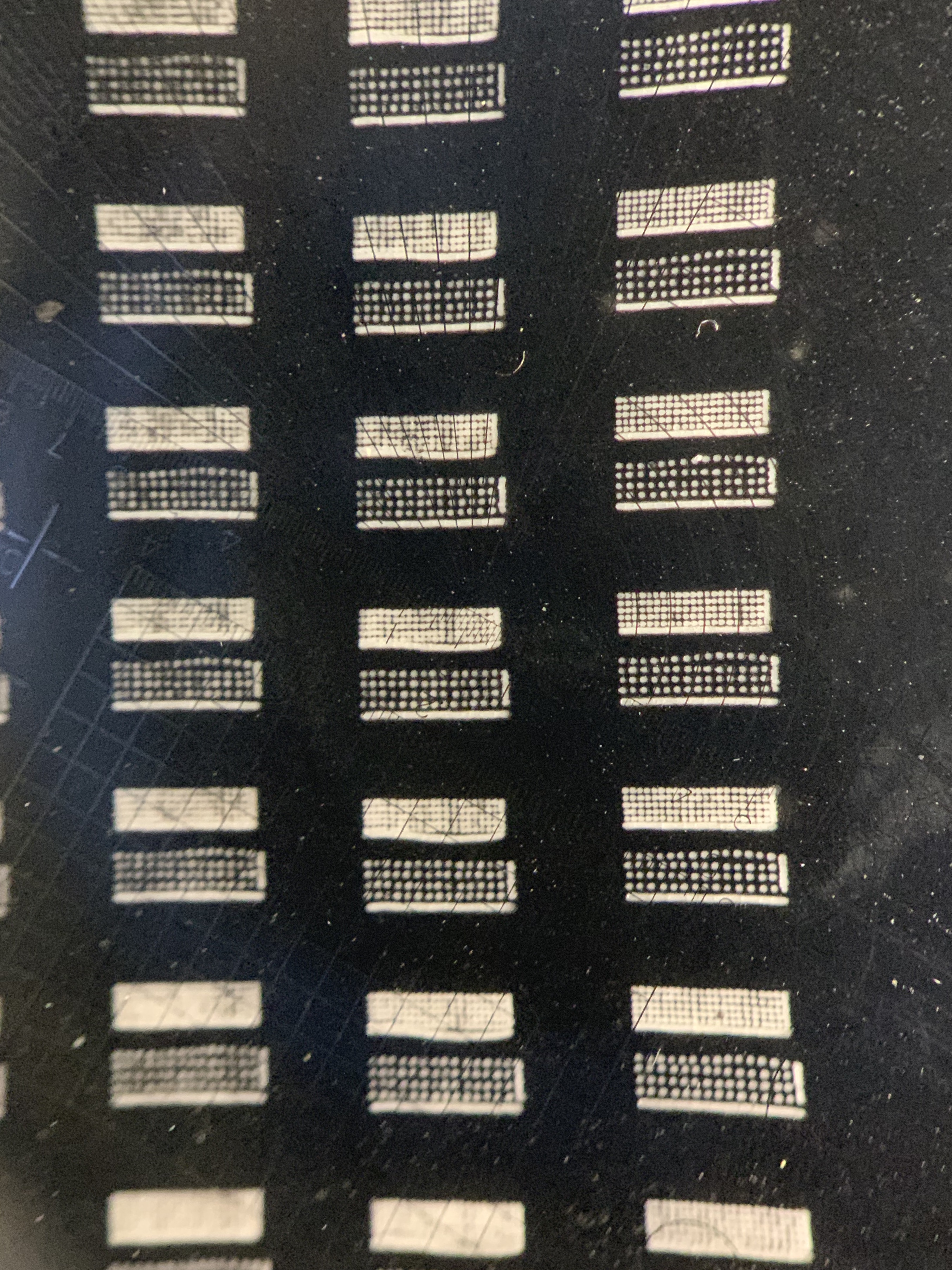
On the never ending quest to tune my laser and see what I can get out of it, I’ve created a new dot test pattern which is below. This image was created at a resolution of 508ppi. If you run it you should do it in passthrough mode so that it is not resampled. All dots/pixels are .05mm.
The tightest pattern has the dots spaced with a center to center distance of .1mm. Each dot has a blank space of .05mm between them.
The next has .1mm of blank space followed by .15, .2, and .25.
I created a file with a power and focus grid with this pattern to dial in my settings.
Dot Test 3.lbrn (398.6 KB)
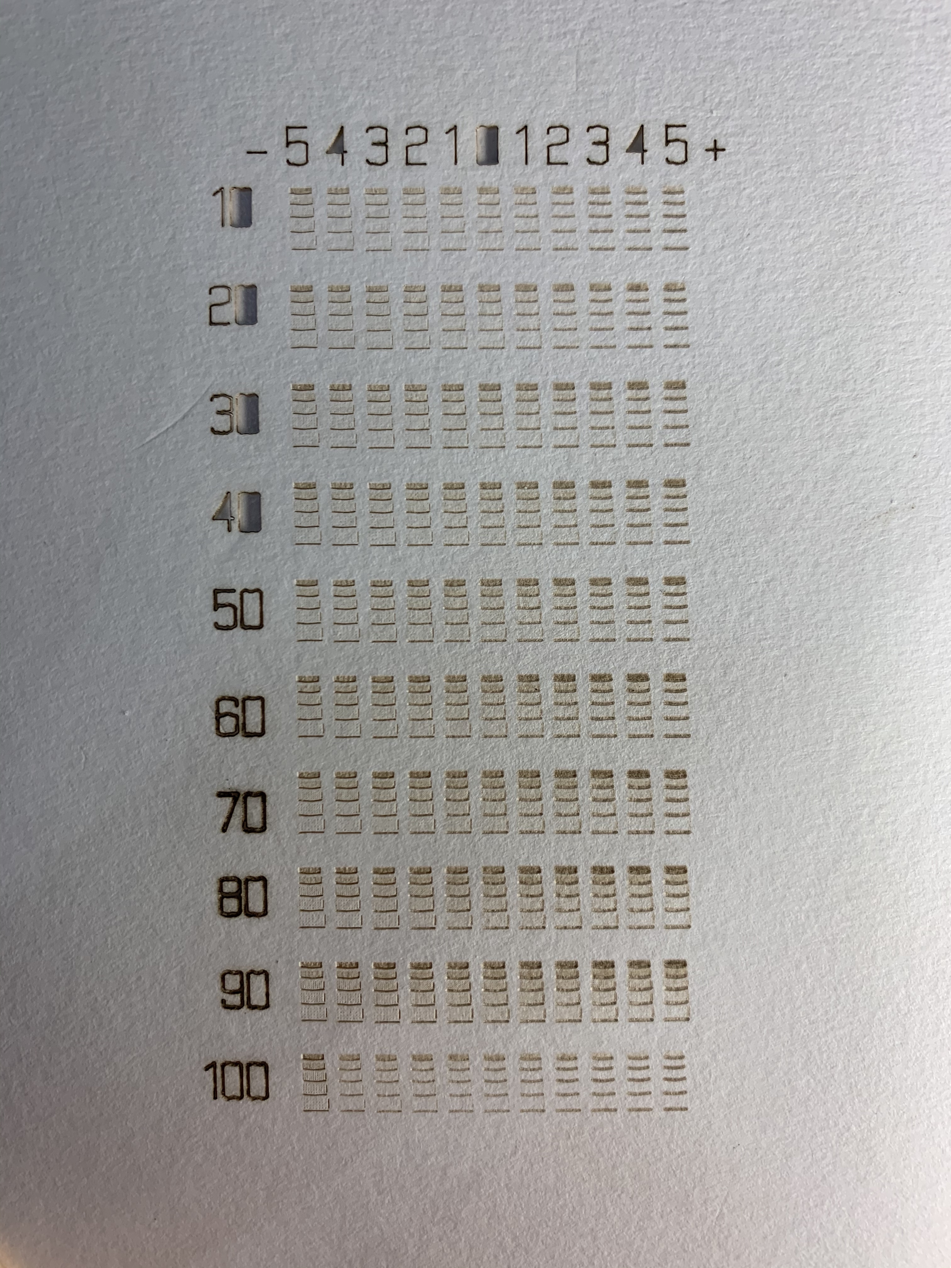
I’m reluctant to post the file but going to go ahead anyway. It needs some modification but I haven’t figured out exactly what yet. So a few things to note about this file. It is a power/focus grid test. The rows should be power and the columns are focus.
I run the standard LB focus test first to get the focus to where I think it’s close then run this. The columns are labeled +5 through -5 with 0 in the middle. With the focus set to what I think is correct, the columns adjust the focus by .1mm. So if the nominal z height focus is 5 mm I set the bed to that. This will run columns from 5.5 to 4.5mm z height using the layer z offset. I use relative z moves only so there is no material thickness set. One thing that I still think is a bug in LB is that the first column has a z offset of -.5mm (out) and the last column is +.5mm(in). But it seems to do exactly the opposite. The positive value moves out/away from the material but the negative value moves in/toward the material. For me Z 0 is with the bed at it’s upper most position closest to the lens and as the value increases it moves down/away from the lens.
The cut optimizations need to be changed but I just haven’t figure out exactly how yet. It runs each grid from the bottom up then moves down to the next row and burns from the bottom up. Think each image just needs the start origin changed. It also starts with the first column, burns down 9 rows, goes back to the top of the second column, burns down 9 rows, then finishes the last row in the first column, and so on. Not sure why.
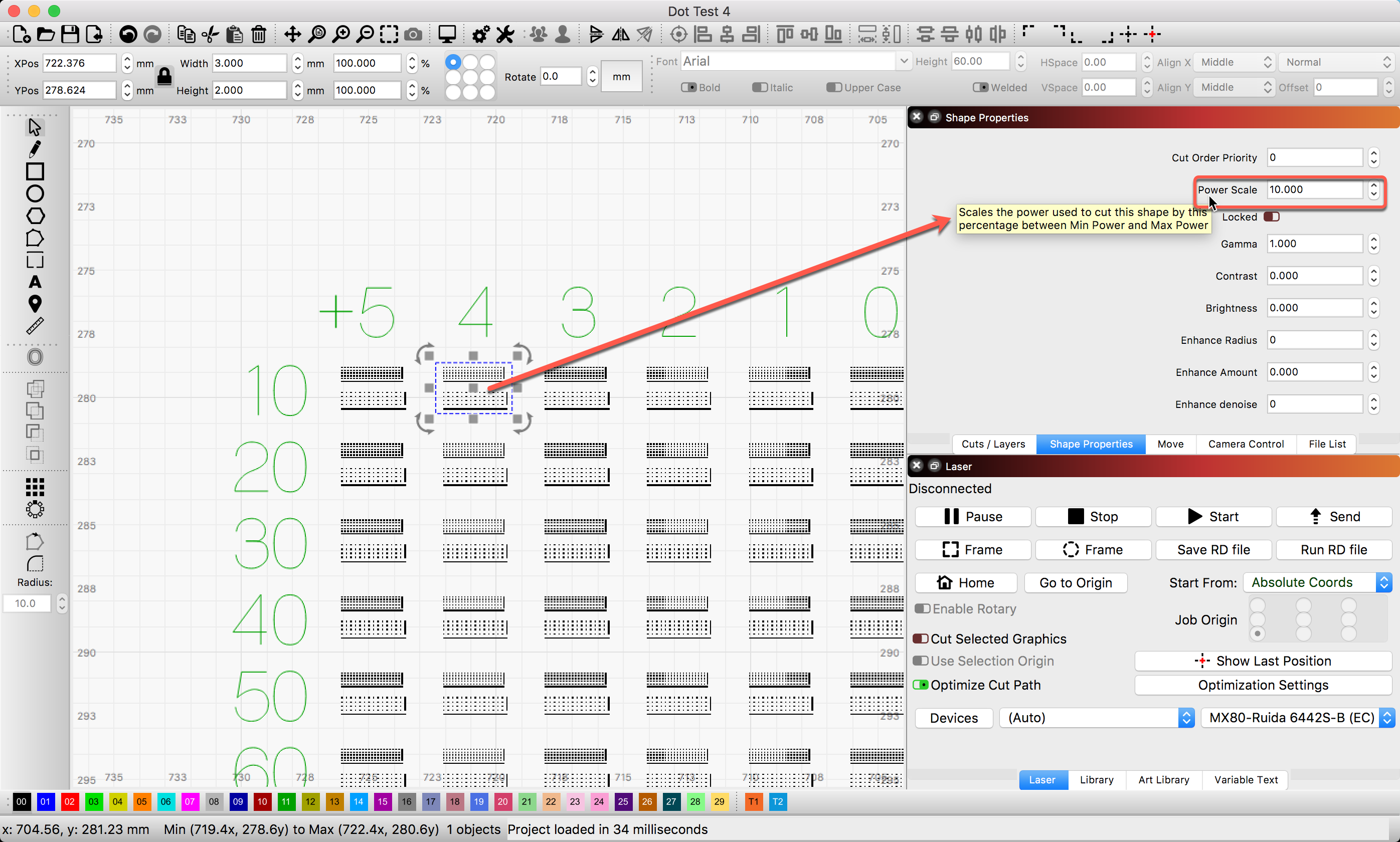
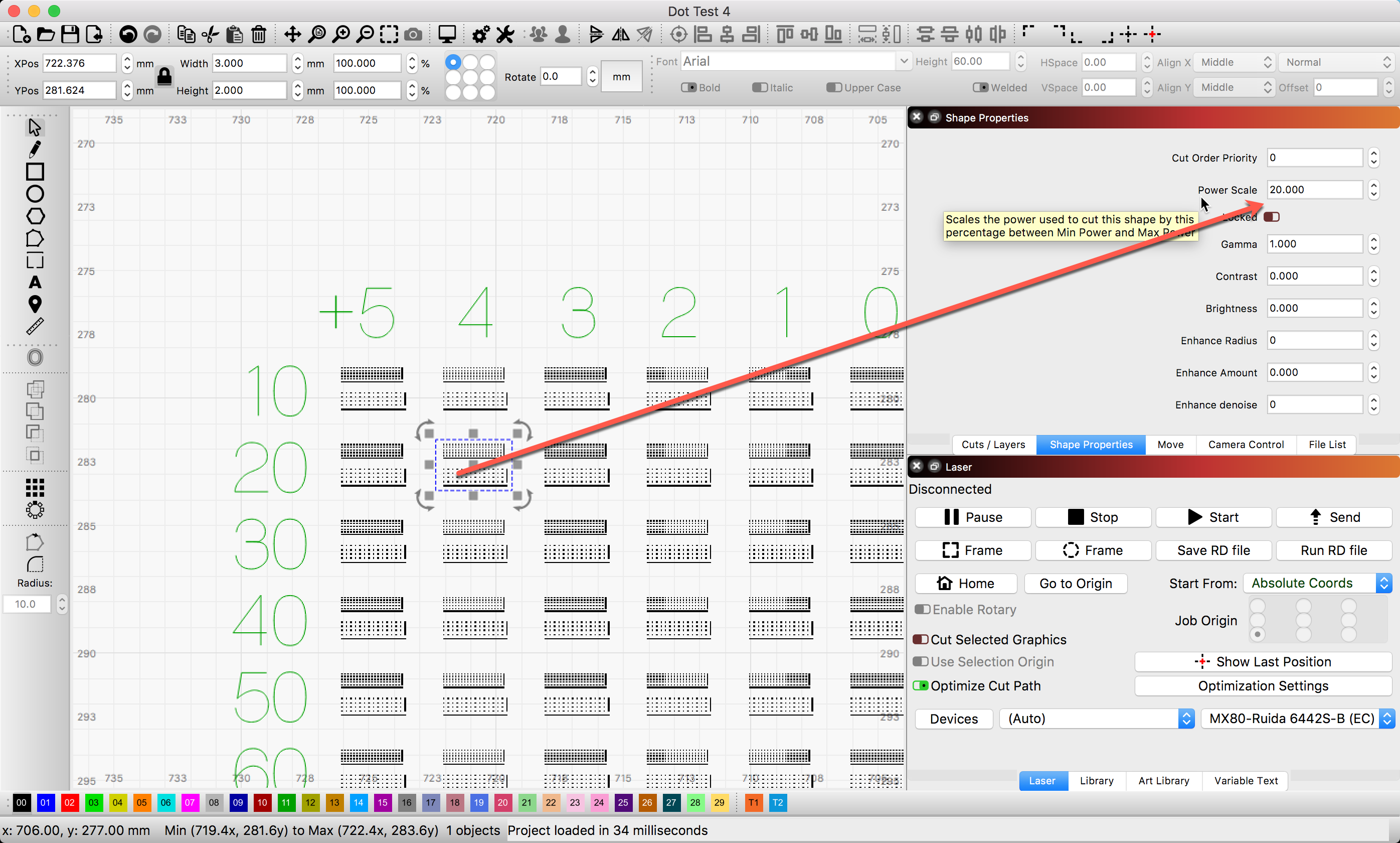
I’m also not sure I have the whole power scaling completely figured out yet. Because this is an engraving test I’m wanting the power on each row to be from 11% to 20%. To do this I have each layer set with a max power of 20% and min power of 10%. I then have the layer shape properties set to 10%, 20%, 30%, etc. I’m not sure I’ve done this right to get the result I want. If anyone has some insight here I’d appreciate it.
So, here’s the file with whatever faults it may have.
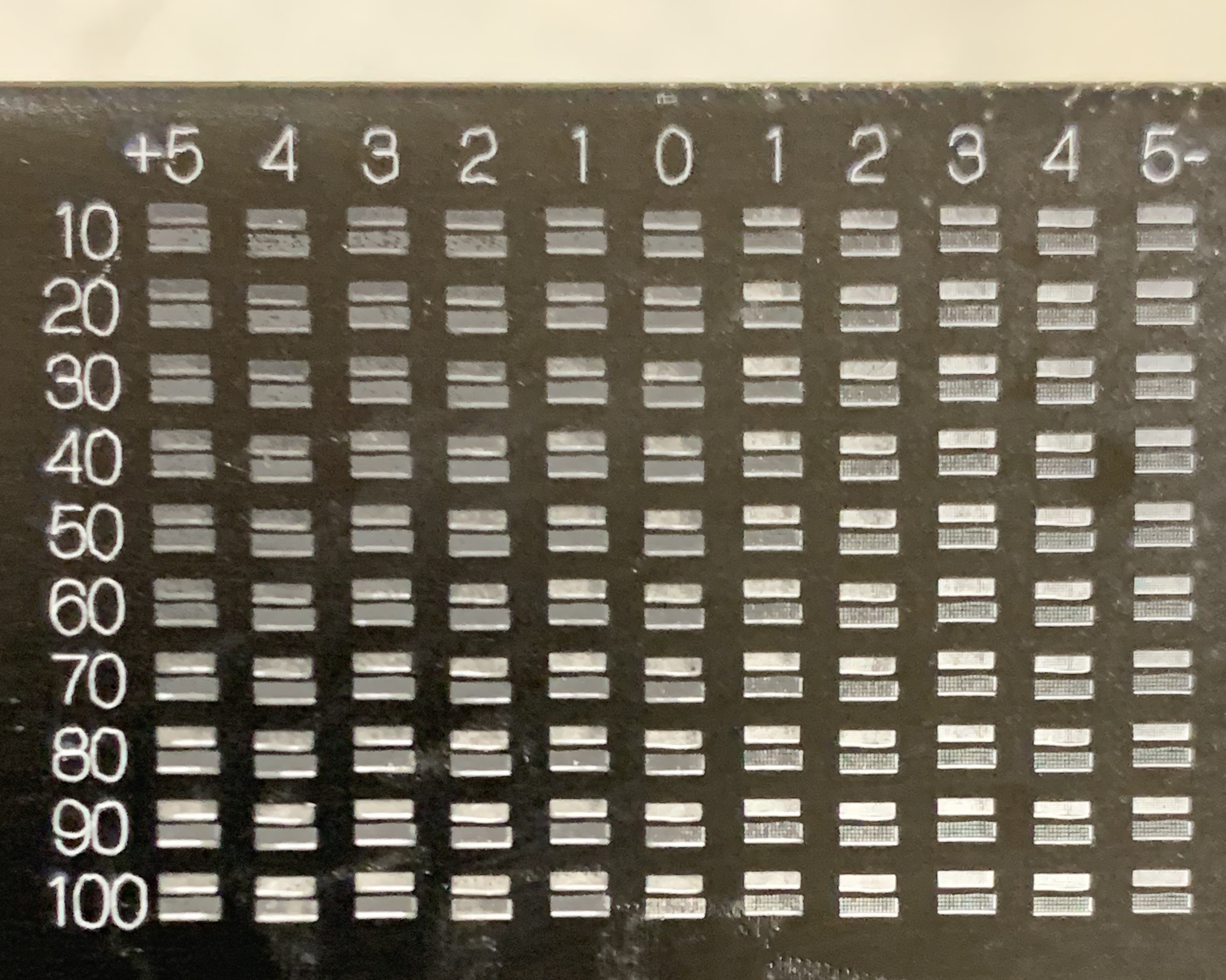
I’m updating the file. I got rid of all but the two smallest patterns since that’s all you should need for this level of testing anyway. I also updated the cut optimizations so that it engraves in a much more logical order. Every other column has the scan angle flipped 180 degrees to reduce travel moves. This is much smaller at 50mm x 35mm when finished and completes much faster.
I’m personally using a 60 watt machine and running it at 100mm/s. The z offset for each column is ±.1mm as it was before with 0 in the middle column. Ideally I’d like to use variable text to print the absolute value of the z height for each column but Oz says can’t be done with Ruida.
The power scale is from 10% to 100% of 10% to 20% if that makes sense. The scaling can be confusing. I also used single line fonts for the column and row labels.
So the 10 row should be 11% power, the 20 row 12%, etc. on up to 20%.
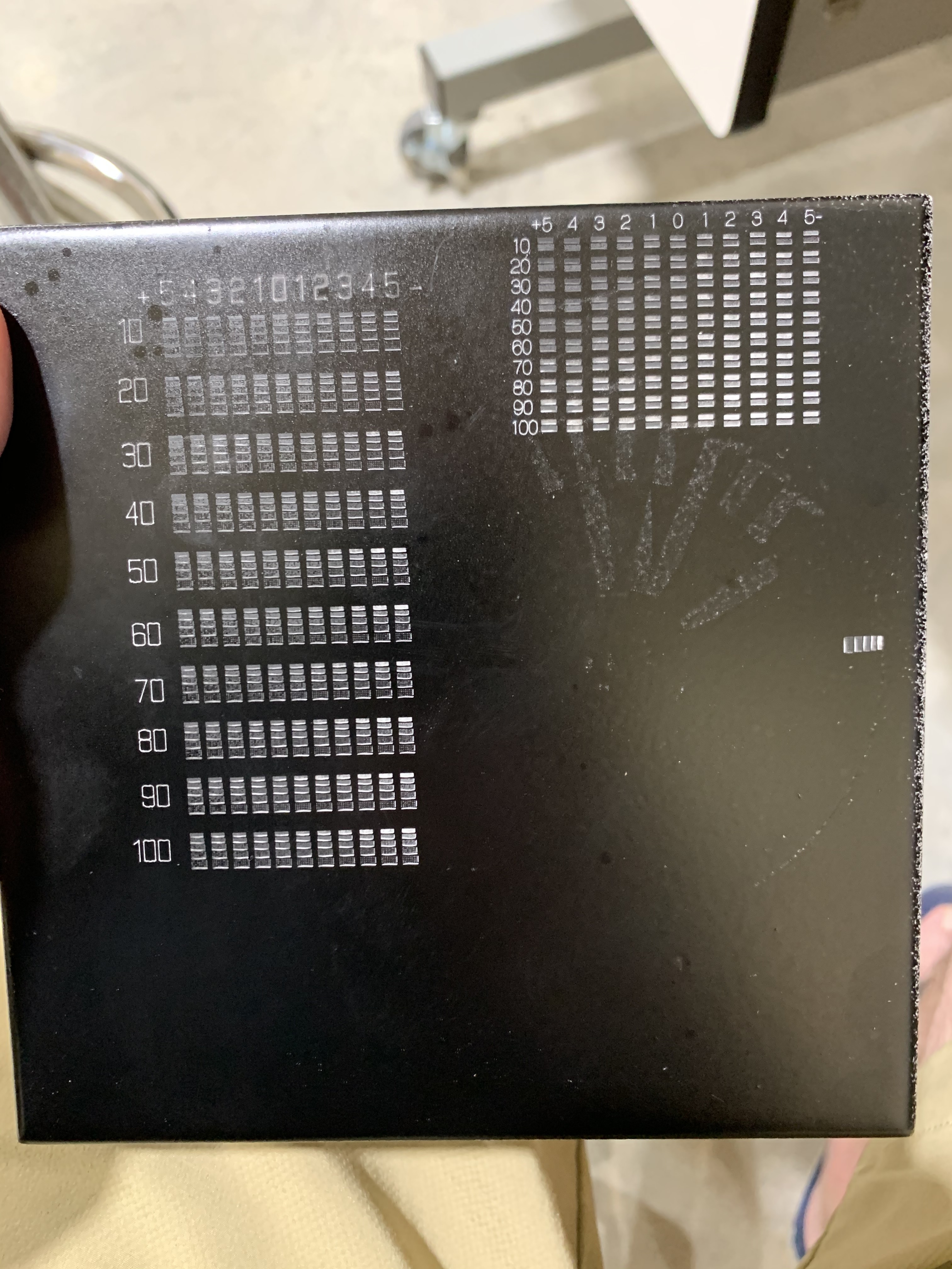
Here’s a pic of a test.
Thanks. I’ve watched all his videos. He gave me the idea to create this pattern. Not sure why he doesn’t take advantage of using Lightburn with his moveable Z for doing his focus tests.
I am confused when i open it in lightburn all the different colors are set to 100 mm/s and 20% power The way it sounds each color for the Colum should be different power settings?
I am trying to figure out my max DPI setting. Sounds like it might not be easy so never mind. There probably is a formula to compute DPI given mm spacing that I could use.
ok, that’s understood
… and I thought that was probably why. I have been in the same situation and have done the test in mm and of course also use this field to set my desired values. (it is the easiest for me especially if you see the conversion factor from dpi to mm and vice versa)