Hello there,
Just got around to installing my new 150x150mm lens for my G2 fiber.
I have cloned the machine and have adjusted the area as per the documentation from lightburn here:
I am trying to run the galvo correction now. The framing for the 9 point test shows it being centered on the bottom left of the machine (0,0). When ran however, the test is run at center of lens (75mm,75mm)
A standard red-dot outlined shape outlines correctly.
Is there something I am setting wrong? Do I need to move the origin to 75,75 to be the middle of build plate? It only gave me an option for bottom, left
I am also having an issue with the dimensions of the objects being engraved.
A 10mm square comes out to be 15.5mm square! Realizing on re setting up the galvo 9 point correction that all dimensions are not matching..it says it will generate a field @ 130mm which is target 85% of max field..it shows up as a 95*mm square when it burns…
The field size of a 110mm lens for 85% target of field size is 95mm…this can’t be a coincidence.
Something is stuck from my 110mm lens import/clone.
Any ideas on what steps I may be missing?
Thanks,
I have tried adding a new laser manually and importing the .cfg file. After it imports, even upon setting the field size to 150mm, it still uses the 110mm settings for limitations of driving the red dot preview and the galvo correction tool as well.
I have to be missing something as it shouldn’t be hard locked to 110mm right?
As far as I know, when it frames for the lens correction, it will use the center of the field. On my fiber, I use the center of the work area and align to that.
When you do the 9 point correction, are you sure the lens is in focus? Generally speaking when you get near the edge of the lenses coverage, the distortion increases. I have 4 lenses and that’s my belief until someone convinces me otherwise.
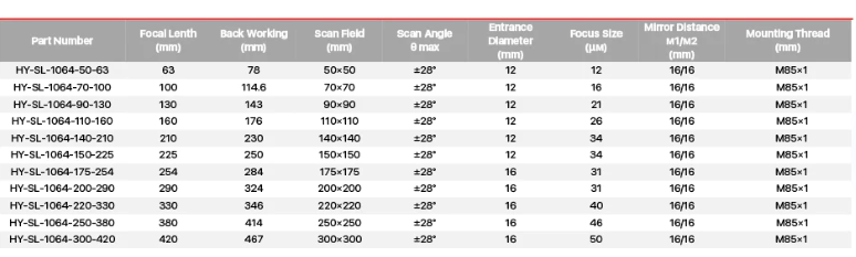
G.weike says it is a 150x150mm lens. It says F=210 which I understand of course doesnt necessarily = field size. The one that came with the g.w 20 is f-163mm 110mmx110mm lens, which the machine seems to be desperately hanging onto those settings.
I ensured the new lens was focused audially before beginning the 9 point correction and followed meticulously the changing galvo lens link.
I seem to be running into some other issue and have had to uninstall the wider field lens and revert to 110mm as nothing was working as intended.
I am unsure if it is a lightburn bug or if I need to go somehow change hardware parameters to make the G20 drop the 110 stuff and use the 150 correctly, which would be terrible for lens swaps.
From my experimentation with the lens I am attempting to swap; the two “focuses” I found were:
Brightest: 247mm to housing. No work seemed to really be done
Loudest: 267mm to housing. Removed easily black anodizization on a biz card
My focus distance for my stock lens is 210mm to housing.
Did you import the configuration file, usually markcfg7 that came with your machine?
These not only have your lens configuration, but also the settings for your source. If you received two lenses with the machines, there should be two configuration files.
I believe these are not stored on the controller. I believe these settings are in your device setting within Lightburn. So they are associated with a specific device.
When I set up a new lens, I import markcfg7 file, then create a cor file for the new lens, or the 9 point alignment.
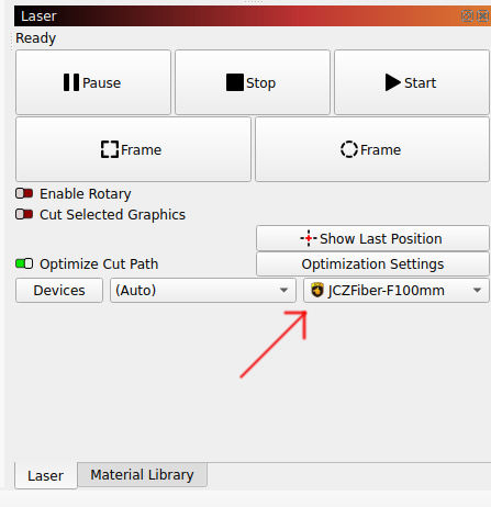
I’m guessing that you are not setting up a new device for each lens. Lightburn will handle these, but I like to export them to enure I don’t loose anything.
I am cloning the device / duplicating it and have importe the .cfg file for the device which for a BSL appears to be a file named LmcPar.cfg There was only one lens supplie with the machine, which had its .cor file and allowed for immediate setup. I have queried them about a similar file for the 150x150mm lens and they insist it is up to me to configure now and no such file exists.
Once the LmcPar.cfg file imports I do 9point correction…however, I can’t get the 9 point correction to correspond to the numbers it says it is showing.
It consistently draws me the 110mm lens config despite me changing the field to 150x150mm.
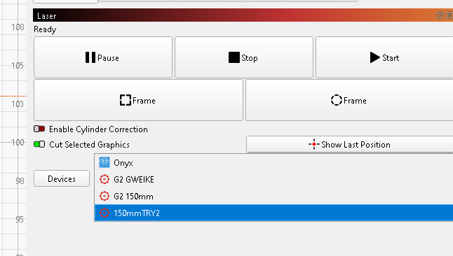
The closest I have got is by creeating a new device from scratch, setting field size immediately to 150x150, then importing the .cfg file. It still draws the incorrect dimension square for the 9 point galvo test, but instead of being 95mm its like 122mm instead of 130. Definitely infuriating
If this works, then there must be something in how you’re configuring the machine with the other lens.
Generally these lenses come configured if you purchase them at the same time with the machine. If you get one, separately, then you have to do the cor file or configure the lens correction. You can still use the .cfg file for your control board.
The EZCad2 software comes with a cor file creator that uses the same 9 point alignment. Don’t remember what it is.
When you go to a longer lens, are you ensuring it’s focused by sound… just double checking.
Hey Jack,
I am ensuring it is focused audially with the longer lens. The initial lens has worked flawlessly and I am using it now after backing out of the upgrade as we speak. The issue was merely I wanted a bit longer of a diagonal to accomodate carbon slides and a few floor plates that exceed 110mm in length quite easily.
I am importing the machine .cfg
Setting field size to 150x150mm
Focusing audially
Running 9 point correction (stuck)
On the STOCK setup, I imported the .cor file that was supplied and it was essentially plug and play for lightburn.
I agree it must be something with how I am confugiring it but I do not see a problem with my process.
I did my lenses using the spousal Windows machine and some software that came with the EZCad2 memory stick. This produced the lens cor(rection) files that I just loaded via the Device Settings.
I have read through the description of the 9 point adjustment and it works the same as the EZCad2 software, but I didn’t see if it created a cor file.
In any event, it should work with your new lens.
Did you make it through the whole setup of the correction even after the size of the squares are not correct. I believe mine were much closer than yours.
We might need to call for external help with this if you can’t get it operational.
Yep I made it all the way through the 9 point correction. I only realized it was off when it shot the 95mm square when it said it was shooting a 130mm square…the numbers I was feeding into the measurements hit my dejavu button and I realized I had entered these numbers before when attempting to setup the initial lens (Before I knew it had its own .cor factory file supplied with it)
Anywho…when it is “set up” the whole thing is wrong. It can’t walk a red line outline all the way to the 150mm mark like it should. It starts warping the square to a weird pillowed trapezoid due to the distortion. It is like the mirrors inside are trying to shoot the beam at the old one. It is SO weird.
I ran a bunch of tests once it was “set up” on some cards. Everything felt wrong with how the laser was acting at different powers. I realize the lens changes the dot size but it just felt incredibly weird like it was something else!
I wish I had better info to provide I just feel I am either missing something specific or the G2 has a weird issue with holding onto settings or something from the old set up despite me cloning and creating new machines that talk to it.
When I burn a square after configuring the new machine with the 9 point galvo correction, the dimensions were still wrong. The tool was incorrectly setting the scale % adjustment on the X and Y axes. This video showed that I needed to hit the 3 little buttons on the X and Y axis under the wrench/screwdriver icon and adjust the “requested/measured” dimensions to adjust the scale of each axis. After 3 tries I finally got my 80mm square to be right on the money. When I first started it measured 119mm on Y by 124.5mm on X! I am now shooting within 0.5mm which to me is my eyes + hands tolerance.
Hope this helps someone in the future…though I am confused why it was not adjusted with the scale galvo tool. There is definitely an issue with the tool as it stands.