New laser power supply resulting in new process

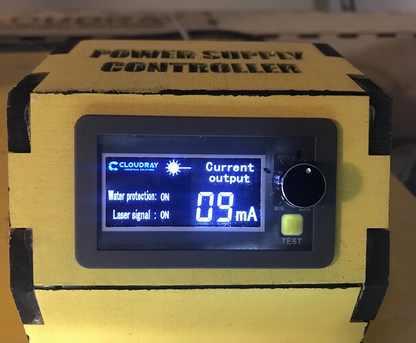
I recently bought a new 100w power supply for my 90w Cloudray tube. The power supply has a remote adjustment for power. I find that I cut paper to cardboard to engrave and cutting that all take different power settings. I don’t like to blast thru materials at full power. So from Lightburn I could need various files of the exact same vector to cover the various power levels.

What I’m now doing is to send all files over with 100% power and then set a lower power on the power supply. For example I needed to make a large cut in thin glued up board. So I have something that’s roughly 300mm square. The pattern barely fits. So I taped a piece of paper down to the honeycomb and ran one pass at the lowest power. Then positioned the board over the paper making sure it would cut everywhere. If it didn’t completely cut thru then increase the power and take multiple passes.

To me each new file might result in a shift in the pattern. So running one pattern or file is safer.

This might be a common feature in lasers btw.

Lightburn already has a power setting. Each different layer can be set to a different power setting. Run a material test to zero in on the exact speeda and power settings to use on a given material. There is no need to manually dial down anything once you understand material settings.

To make it simple let’s say you have a large square. You can only set one power level on that square at a time. Correct? I can change the power level and send another file to the controller but then I have two files, one for cut and one for engrave. I’d rather have one file on my controller. Then run the pattern at what ever power I choose. That’s my point.

I suggest people not use these until we figure out how they work. Most plug into the lps and there is a switch to allow the control.

There is only a single input to control current with an lps, so how it works internally is still in question.


I’ve had suspicions that this is implemented like the K40. Something similar but using the pot (control) to set the IN voltage (maximum current). Then they run the machine like it’s a dpssl.

I’d rather run my tube at 50% power for 100% of the time rather than 100% power for 50% of the time. If the analogy is correct, you run 50% power, whatever is displayed on the meter is 50% of the actual current. In this case if it were 50% pwm (power), you are reading 18mA.

Good luck

:smile_cat:

Jack I don’t understand the concern but since your concerned, I recommend that you contact Cloudray and raise it with them.

Saying something is unsafe without an opportunity for an explanation amounts to misinformation, which is all over the news these days. I’m sure their engineers are NOT monitoring forums like this. So far I’ve had good experience with anything I bought from Cloudray and I hate to leave folks with any negative impressions, without something to back it up.

This is the unit as I’m not sure about the link:
“Cloudray 100W MYJG CO2 Laser Power Supply With LCD Display”

Thanks.

I’m stating an opinion.


Simple fact is they could end up jailed for giving us any technical information.

Everyone out here would love to have a schematic of the lps they use… Impossible to come by… There is one K40 lps schematic floating around, but never have seen anything else.


These lps have an internal current limiter, usually with a 20 turn pot… This is the proper way to set the current limit…

How could they implement this effectively and still have it work like the internal current limiting circuitry.

The basic design of this equipment makes that kind of adjustment not necessary.

I’ve not only read, but seen a bunch of bs from companies like Cloud Ray and OMTech that is obviously and clearly false. If you wish to believe them, that’s up to you.

I think @ednisley has one of these… maybe he can chime in and advise us if/how he uses it or doesn’t… He also has a current probe.

:smile_cat:

If this is about internal circuits or past issues you might have had about Chinese companies, we aren’t going to solve anything here.

As far as overdriving the tube (my best guess as to what we are discussing) I see the current going into the tube on the display. I don’t understand why that would be wrong. Anything I send the tube, rather it be PWM IN or this potentiometer, I can’t drive it over my max target current. 100% in Lightburn and pot full CW and it reads 18ma. I control that in the laser controller.

So if it’s something I’m doing then I don’t understand the issue. If it’s internal circuit issue then it is just your opinion. However if anyone else has had safety issues with this or any other LPS please let us know.

No this isnt correct. This isnt how gcode or controllers work. It doesnt sit there sending a bunch of individual files to the controller…it sends one. And is full of lines of code, which are interpreted into machine language (HLA) to physically send commands to a control board that forwards them to motors and an on off for the beam…I think youre messing around with something you shouldnt, and its going to cause you headache down the line, especially if you use a co2 or higher laser. Power is already controlled by the driver software. There is already a physical override for the power, its called the beam attenuator.

I don’t think your reading what I wrote clearly. No use explaining anything. One or us mansplaining is enough.

Absolutely…

Depends on what/how they are measuring things.

If you measure a ttl pwm signal out of the controller, it won’t read 5V at 50% pwm, it will read 2.5V

We know there is only a 0 or 5V signal present. It’s probable you are doing exactly this.

The system is designed for software control, I.E. via the pwm → IN of the lps. If you wish to override the standard co2 software power controls, that’s up to you. The K40’s are wired this way… just like a dpssl.

If you can manually set the current, it will draw that current anytime it lases. The IN terminal of the lps sets the current limit, the pot now controls the current limit, not the pwm. Pwm controls the power/time in this configuration.

I go to their site, although not daily. I’ve seen many inquiries directly about these meters how they work and how to use them. They are very consistent with the replies, they will not tell them anything other than plug them in. The don’t even send a manual with them or have any documentation on them.


I only bring this up because a glass tube co2 is not meant to be driven like an dpssl.

I’m only suggesting this to you to extend tube life and be easy on the tube by not lasing it at 100% power every time it lights up.

The choice is yours… as always.

Not clear here, what you mean… Maximum current limiting is a hardware function within the lps.

This will synchronize 100% power/current with 100% (power) pwm. About as close as you can come to linear.


I’m attempting to give you a heads up … not pi** you off.

How do you set this knob for a default? You see this question on the Cloud Ray site pretty often.

Good luck

:smile_cat:

I posted sometime back that max current (my term for it) is like 70% of the tubes max current rating. So it’s my ‘target not to exceed milliamperes’ that I set.

On the what is the output of the LPS question. That depends on the dial. Kind of like a feed rate override on an old milling machine. Probably not something you would want on a machine in a business. But I’m not worried about that.

On the unknown circuitry, I wonder if the dial is just a voltage divider on the PWM IN signal. Anyway I think I gained a better perspective of what others are considering from this exchange.

I wouldn’t think so, that would compress the pwm actual range.

I think it works like a voltage divider between ground and 5V with the wiper to IN controlling the current limit.

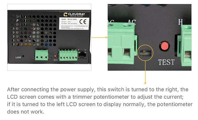
From their wording of that control, it states that if the switch is to the left, the pot has not control, if to the right the pot controls the current.

They can’t be too complex, they sell them @ $9 each.


Of course … my opinion…

:smile_cat:

OK, now that I’m awake … :grin:

IMO, the only disadvantage of twiddling the knob for each job is that you’re depending on remembering to set it right every time, which seems unlikely in the long run, and you’re giving up the ability to automate the current for different layers.

I have a similar remote display for a 60 W Cloudray supply, but (as described in the doc) the knob works only for supplies over 100 W with an internal switch enabling remote control. From what everybody with such a supply reports, the knob scales the current between zero and the maximum set by the supply’s internal trimpot, which is what the supply delivers without the remote display / knob.

Given that the supply already has a current control loop based (AFAICT) on a sense resistor in the cathode lead, the switch inside the supply probably selects either:

  • The output of the feedback control amplifier
  • A fraction of that output set by the knob pot.

That signal then controls the tube current as usual, so the knob can only reduce the current.

With that in mind, I think it makes more sense to use LightBurn’s control over the current / power limits, because then the project includes all the information required to run the job without having to twiddle the knob to suit.

For example, my LightBurn job for a set of earrings has three different PWM values for shapes on different layers:

  • Milling a rebate around the rim
  • Kiss-cutting a surface reflective layer
  • Cutting the perimeter

With the power supply’s internal pot set to the tube’s maximum current, a single job applies the appropriate currents (and speeds) without manual intervention. It’s not clear what advantage a knob would bring, as I rarely need to change the power during a job, and reducing all three powers by the same percentage seems like it wouldn’t produce consistent results.

In fact, I rarely want to change the power, because I’ve already put the lowest power to achieve the result in the Material Library, based on previous tests. So, using your example, I select Art Paper or Cardboard → 3.5 mm or Acrylic → 1.5 mm to apply the appropriate power for whatever I’m doing, with no need to remember any of the numeric values.

But, for sure, other folks do it differently! :grin:

I can’t imagine why anyone would want to even try using that thing for controlling output for every job. I have one on my laser and it is good for limiting current but the Ammeter display is useless. The sampling rate is about once per second. I set mine to limit the current to 26mA by using the pulse button and gradually turning up the current until I reached my target. I verified the reading on the display with another Ammeter and it’s spot on, but it’s so GarrdDernd SLOW!

Ok thanks all. I’m not hearing that anything is unsafe about the way it works, just not something you would find useful. Not hearing any K40 references. Not going to explode or anything if I turn the knob?

I understand that with multiple vector power paths lowering the power would affect all cuts which is not what you want. I agree. Also the issue of not recalling what setting your on, or not noticing is also a potential issue.

On the accuracy of the display I’ll have to hook up my old method of measuring power and double check it. They don’t both display at the same time I found out. It does have a slight delay but that doesn’t bother me.

On the point of having material settings in the library I got that but each setting is another file to the controller. My point is that I can lower a high power cut to do pretty much any material. I’m not on a shop so I can operate it less by the book, which might not work for others.

Thanks.

With the power issue settled, something else occurs to me:

If that’s the case, then you should solve that problem before doing anything else.

I routinely align to a fixture, then run several “files” or jobs or whatever on different blanks in the fixture with that same setup and no problems at all. A large CO₂ machine should home accurately and never lose its position thereafter; if it does, something is wrong.

Has the machine actually lost its position between two jobs or is the word “might” just a figure of speech?

1 Like

This is also supposition, like my assumptions. :crazy_face:

It being Chinese, I would still bet on it being cheap, quick and dirty, which eliminates most of the speculation. All you find is people bashing the Chinese junk we get, now all of a sudden these people are standing up for them … I’ll have to see it to believe it.

The piece I posted stated the pot now controls current… Nothing about basing it on the original setting.

Too bad you can’t hook one up, I’d like to see the current draw…

:smile_cat:

They are useless, at least as an Ammeter. Mine works fine as a current limit, but otherwise forgetaboutit.

I may have missed the instance where someone with a remote display mentioned it increased the current beyond the normal setting.

So let’s (try to) find out.

I assume the display will show the output current even with the knob disabled by the power supply’s internal switch, because Cloudray sells the remote display for power supplies without the switch. That’s how it works on my 60 W supply: the remote display agrees with the supply’s digital display.

@dean448, would you be so kind as to do an experiment for us?

Does the TEST button on the remote display turn the laser on at its maximum current or to a level you set somewhere in the controller’s menu tree? If possible, set the TEST current as high as it will go.

Turn the knob fully clockwise, fire a manual pulse, and record the current.

Flip the internal switch on the power supply to the other position (thus disabling the knob), fire another manual pulse, and record the current.

For completeness, with the knob still disabled, turn it fully counterclockwise, fire another manual pulse, and record the current.

If the knob behaves the way I think it does, then all three currents should be about the same, either the 18 mA you mentioned earlier or whatever the supply’s maximum current is.

If the knob behaves as Jack describes, then the current should be higher with the remote display enabled and the knob turned fully clockwise.

Thanks …

Here is what I found ednisley. I hope I followed your instructions.

So I have two meter conditions:
Old amp meter: M1
Meter attached to LPS: M2
Call the pendant attached to LPS: P1
Knob on P1: CW is full power. CCW is no power.

If M1 is attached to the cathode then M2 shows zero
If M1 is not attached then M2 shows values

M1 connected and P1 connected
Full CW on knob I get 7 with either the controller test or the LPS test button
0 for full CCW
Full power cut: 20

M1 connected and P1 disconnected
Same as above so P1 disconnect equals CW
Full power cut: 20.9

M1 disconnected and P1 connected
P1 shows 5 to 6 on either test button
Full power cut is 18 on P1

When P1 is connected I get zero on full CCW for either meter in either test or full power cut.

About the only thing I’m learning is that the M2 reading is about 10% lower then M1. I really don’t know which meter is accurate. M1 was purchased a long time ago for my first tube and LPS.

Hope this helps. Nothing blew up and no animals were harmed during this experiment
:nerd_face: