Also explained in the documentation here: https://github.com/LightBurnSoftware/Documentation/blob/master/CoordinatesOrigin.md
Thanks Rick & LightBurn!
Wonderful! That is the precise information what I was looking for! Great video and explanation Rick! Thank you gentlemen! 
I think this might work
and have one in the post and hoping to use with this
to add limit/homing switch.
Thanks for the links, I really like that second product of the “support board for limit switches” Thanks!
You do?
As opposed to the $3 board that does the whole job as a full cnc controller with limit switches?
Do you guys measure functionality by howexpensive stuff is?
Hi Bonjour, the answer is yes & no, but since I do this for a living and not a hobby - I keep my options open for future configurations. I have a full working computer lab / fabrication lab ( term used before “maker’s space”) It is a shared space among other practicing independent engineers. So its always good to have a supply of various boards.
Greetings,
I think my laser diode just went out. I ran a small job and it pulsed with the fan and, I’m not sure if I unchecked or turned on or off a feature on lightburn for this to behave this way.
I then checked the laser diode with a dc variable power supply and to my surprise the laser works, so I am guessing that its the step-down driver board that has gone bad perhaps, but I don’t see how.
As anyone experience this with these Chinese engravers?
That 3$ board doesent do all that as it needs an arduino and driver, leads etc (i dont have the techy word as a beginner) and for a beginner it most probably best to stick with standard parts that you may be able to get help on rather than a unique system that you will have to figure out most yourself.
I have a diode laser VERY similar to yours. I stumbled across the “Ks0288 keyestudio CNC GRBL V0.9”. I use it with GRBL 1.1 and Lightburn. It’s got all the standard i/o, plus an extra Y output for 3D printers with 2 stepper on the Y axis. Its just an ATmega328P, and drivers cost extra. But it works great, is easy to connect to. 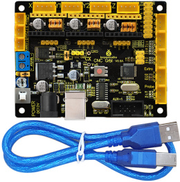
Hi Eddie!
Its funny, I stumbled on the same board and have been using it on my Chinese laser. Although my plan is to build a enclosure for my laser. Have you added your limit switches yet to your board. If you have can you let me know how you set the new engraving parameters in settings? Any feed-back is appreciated. Thanks.
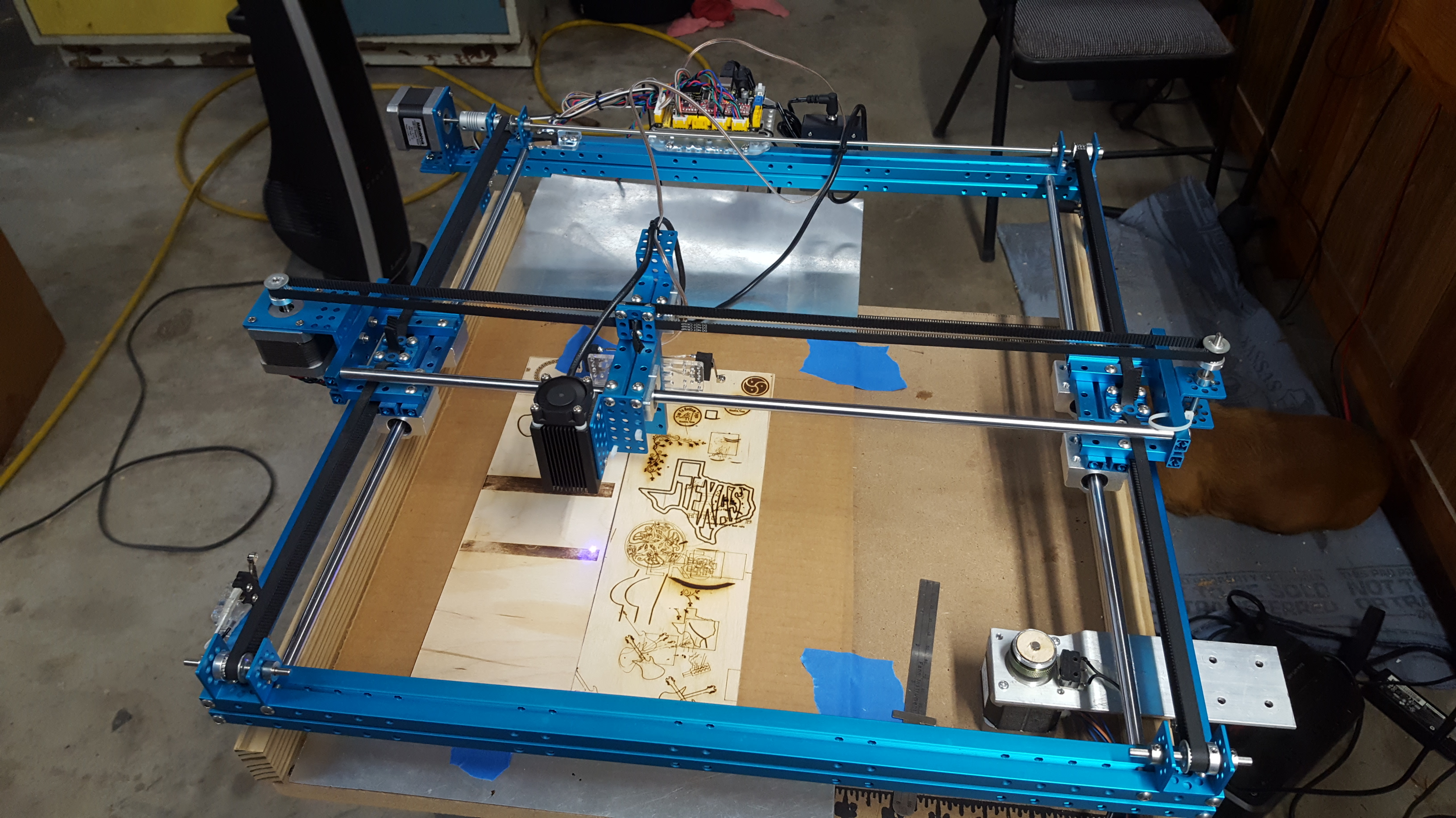
Also, I like that aluminum frame on that laser! It seems to have a solid movement and zero loss on the engraving value. My laser frame rides on plastic rollers that are guided along the aluminum bars - and often get a little noisy and need to blow off the dust on the tracks that they ride on. BTW, what is the name of your laser engraver?
It was an educational kit by MakeBlock. Non standard aluminum extrusion.
I’m not sure which settings you need. Elaborate please.
Makeblock mostly use OpenRail/V-rail - but that looks different.
V-rail is great. I’ve built all of my machines using it.
OpenBuilds owns the dies, but there are a few makers of it now.
I use that to frame up prototype instrumentation, but never built a laser out of it.
Sorry for the late reply, I meant the insert connections to plug in my limit switches. Sadly my board came with out instructions or diagram of these connections. Thanks for any feedback.
As you are a professional, not a hobbyist, with a ‘full electronics lab’ I don’t my decades of experience will be of any help.
Should be a doddle, what with all those engineers on hand.
Good luck solving such a basic problem.
Bo, please refrain from answering questions if your answers are just going to be abusive. You’re being an ass, and will be removed.
Great! Thanks for the feedback!
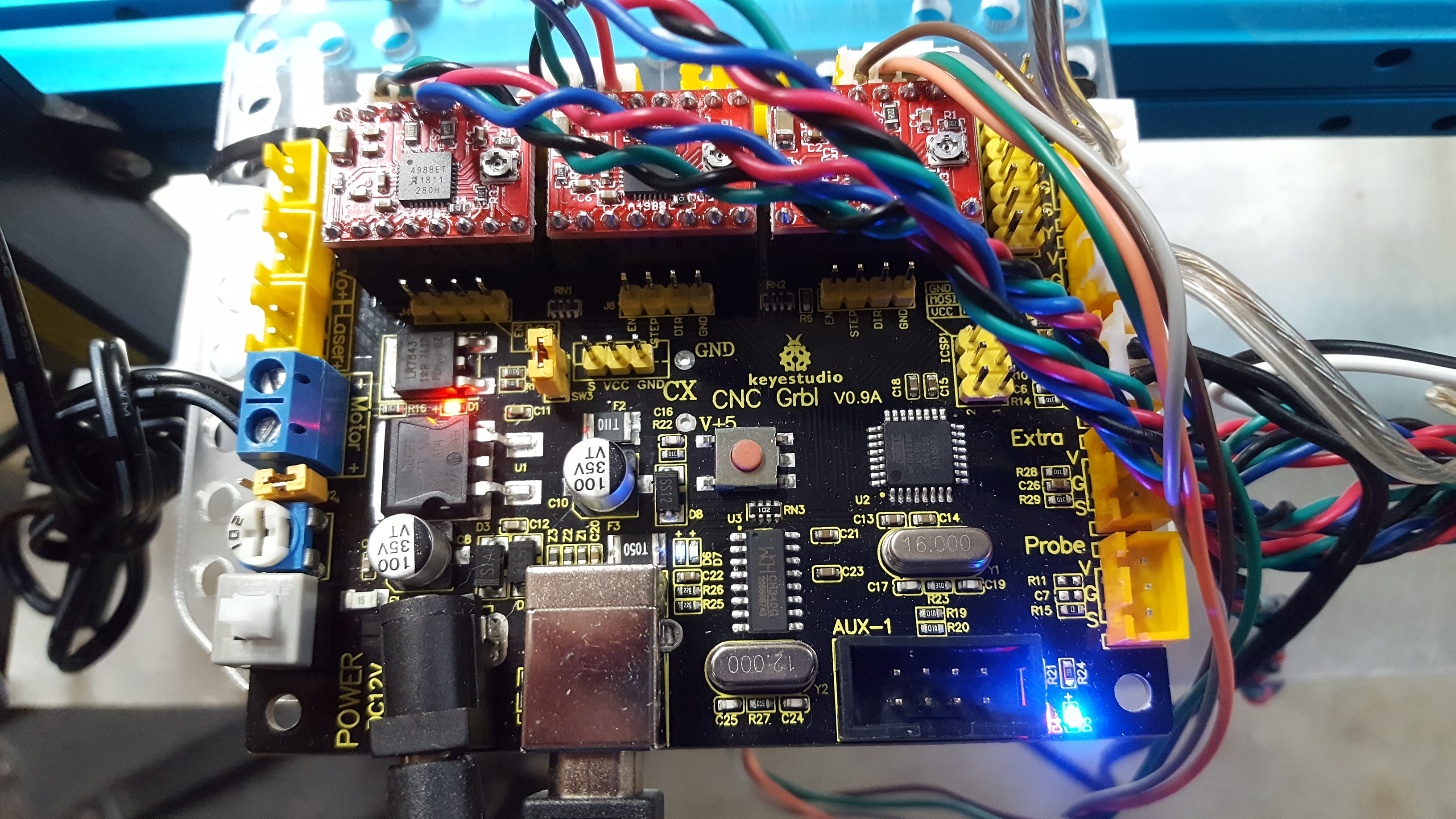
For those limit switches, I use 4. 2 on each axis. The two for each axis are wired in series through the normally closed pole and common on the switch. To the right hand side of the board, there are five yellow, 3 pin JST connectors. Top right is X, pins are 5v, ground, and signal. If you’re just using a passive micro switch, just hook to ground and signal. It just forms a loop through the two switches for each axis. First connector is X, second is Y, third is Z. Forth says “Extra”, and the fifth connector is the Z probe. Does this get you started? I wired my own connectors and so I cannot tell you for sure a plug and play option, but you should be able to buy limit switches with JST’s on them, rewire them in series, or get the JST crimp kit with tool.