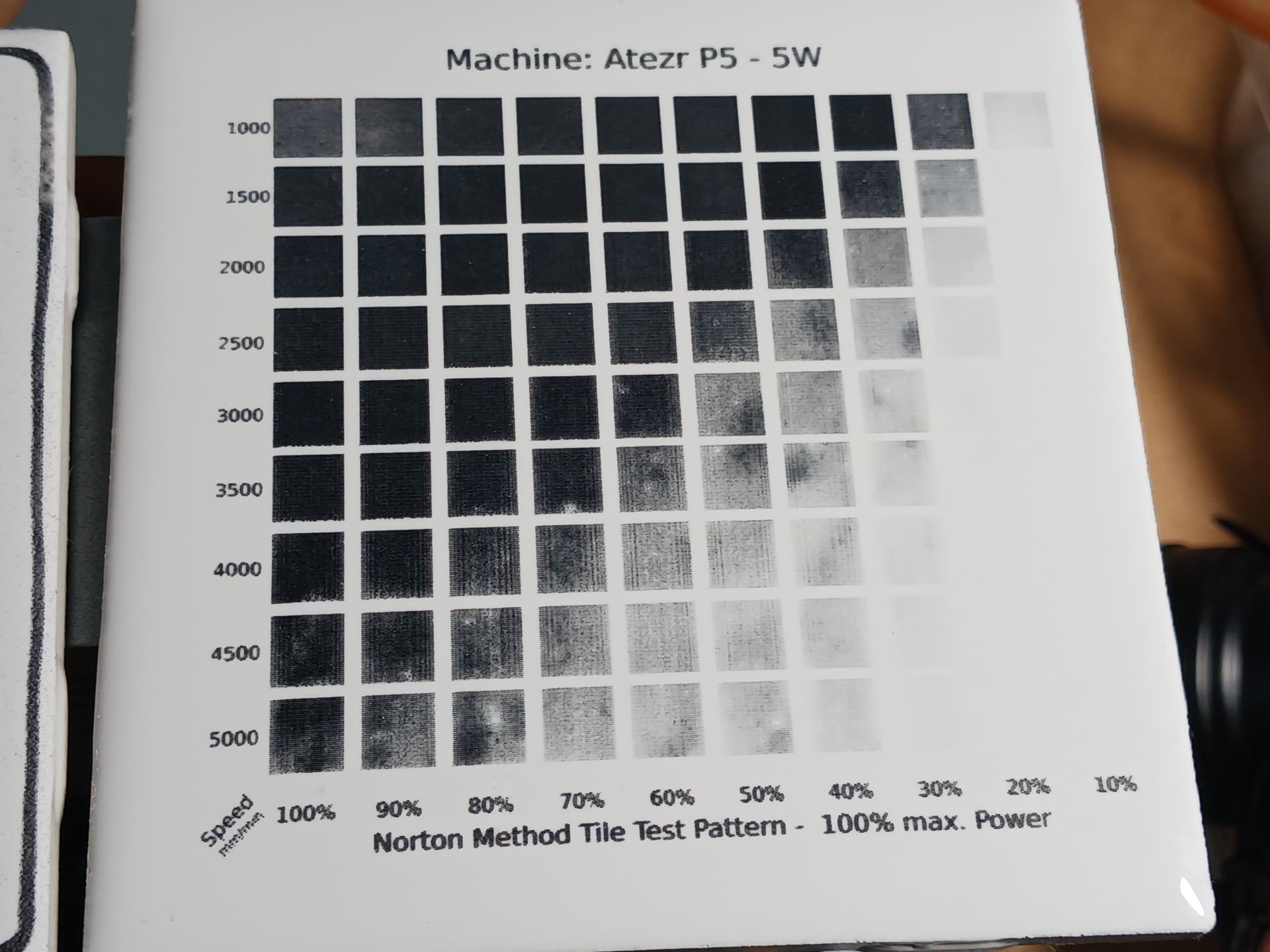
Been following you…
Thanks for the post and procedure you are using 

Been following you…
Thanks for the post and procedure you are using
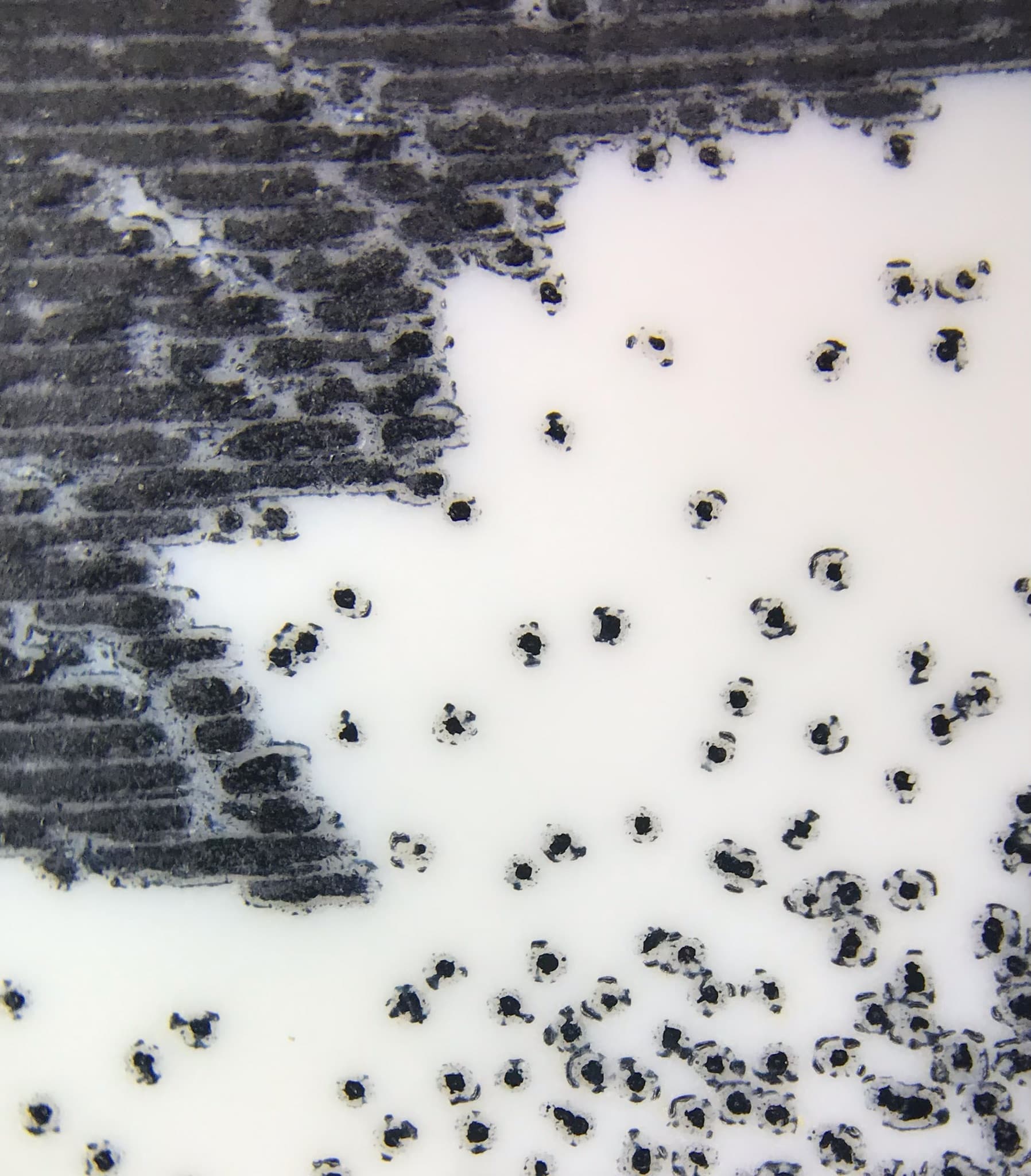
Got a microscope lens for the phone. Closeup of the dither dots. Individual versus a more solid black area.
Thats cool! I like how it looks like a little explosion at each dot to mark the ceramic.
Nice photo… I have a microscope that I look at damage from the laser quite often… it’s the best way to ‘see’ what it’s really doing.
It’s nice to see the continuous black…
I have problems with this kind of consistency.
Thanks for the photo…
I have a 5w FoxAlien laser, can anyone give me settings to use this method with? I’ve tried the Norton White but it does not give the color or effect I want.
I would try for something like 1200mm/min 80% power just as a baseline with what I was running when I was running a 5W diode. More important than the power/speed is having the focus set as spot on as possible. With a 5w it’s possible to get good results with a marginally focused laser if you overpower it (eg 80+%). However, this will affect your image quality in the end if you’re trying to do fine/ detailed raster engraving.
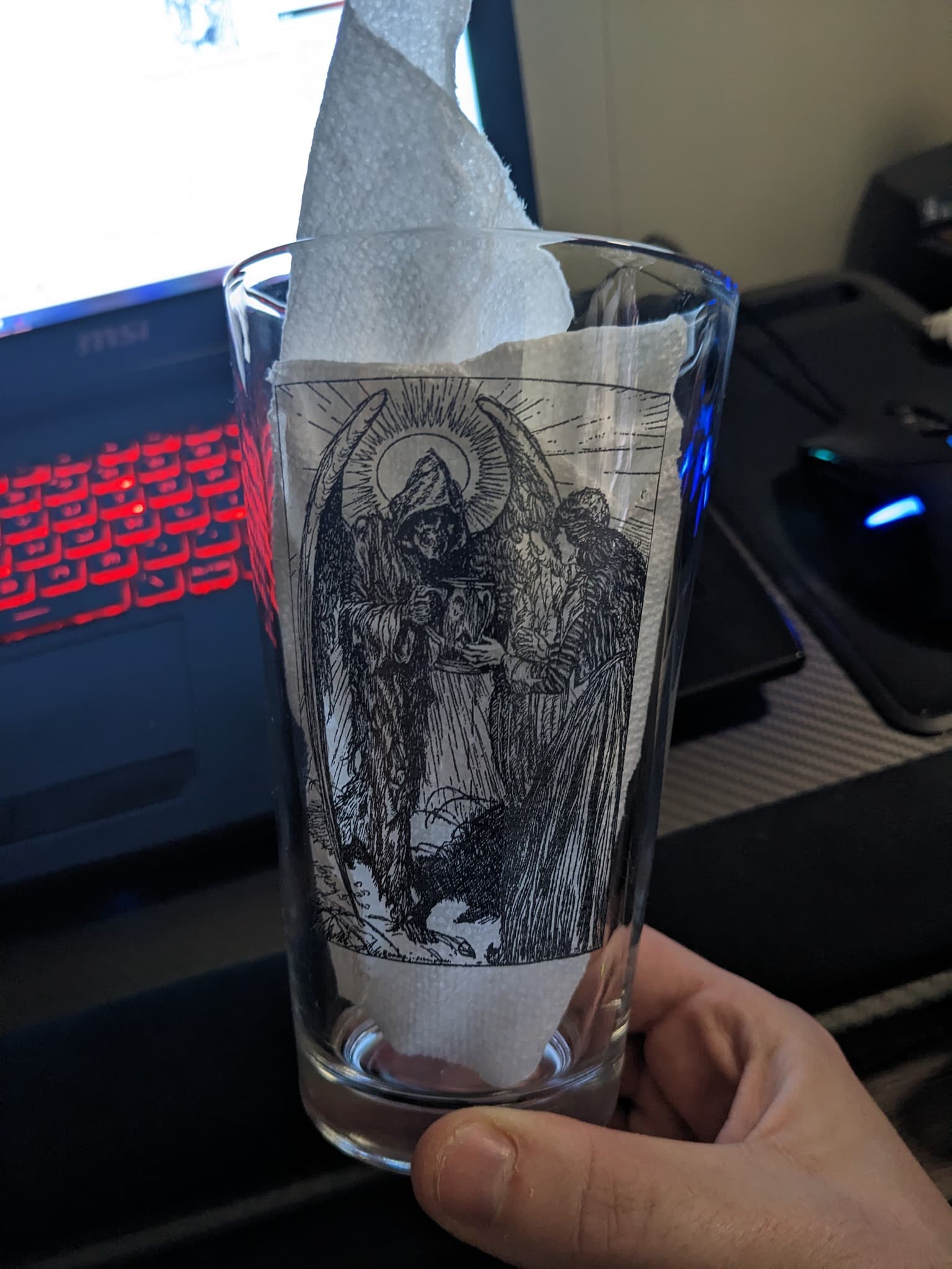
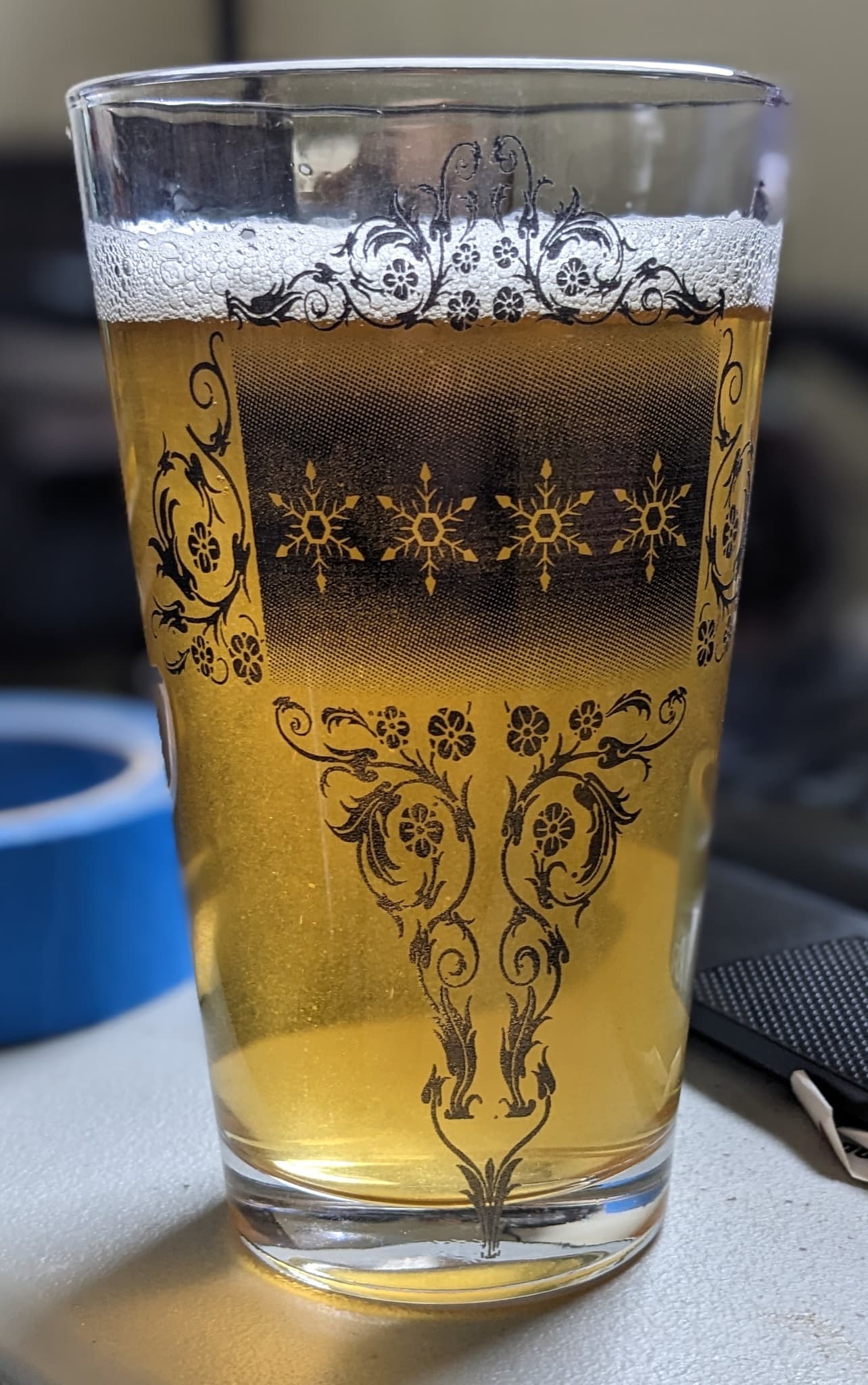
Hey so I have been pretty out of the laser game for a few months with life happening and what not but over the holiday I got myself a rotary and started working on glass, in case anyone was wondering using this method works great on contured glass products.
I’m still a bit new to this whole glass / rotary thing but Ive been learning the ropes. I have found that 3 hoppers of my airbrush provide a good coating across the entire work area and that 1500mm/min provides more consistent results than 2000mm/min. Recently I have been using an Atomstack S10 and running at 50% power. The first image is a raster, second is a vector both ran at 254 dpi. and 2000mm/min for items pictured.
Now that I have started to get more consistent results I am going to be trying to push down the number of coatings.
Nice job. They look great!
hey, thank’s for the advice
I’m trying the water/PVA/TiO2 solution and it works well with my 4W diode laser but having problems with a 60W CO2 and was wondering if people found 2 or more coats works better with higher power machines?
The CO2 laser has a minimum power setting of 10% and so far it just vaporizes the coating. Going to try 2 coats tomorrow and reducing the DPI from 300 to 150.
Im.curious as well if this is doable with a co2. I kn ow the dots a bit larger but still curious on settings.
I do these on the co2, at least used to… never on my dpssl.
On the co2 my power is down around 10 or 11% and my tube is 40W… You’re probably running 50% more power than I did.
I found with too much power, it just seems to evaporate the TiO2. I don’t remember the interval I used, but it might be part of the problem.
If you are at your power minimum, then your only options are to try a larger interval and/or go faster… 
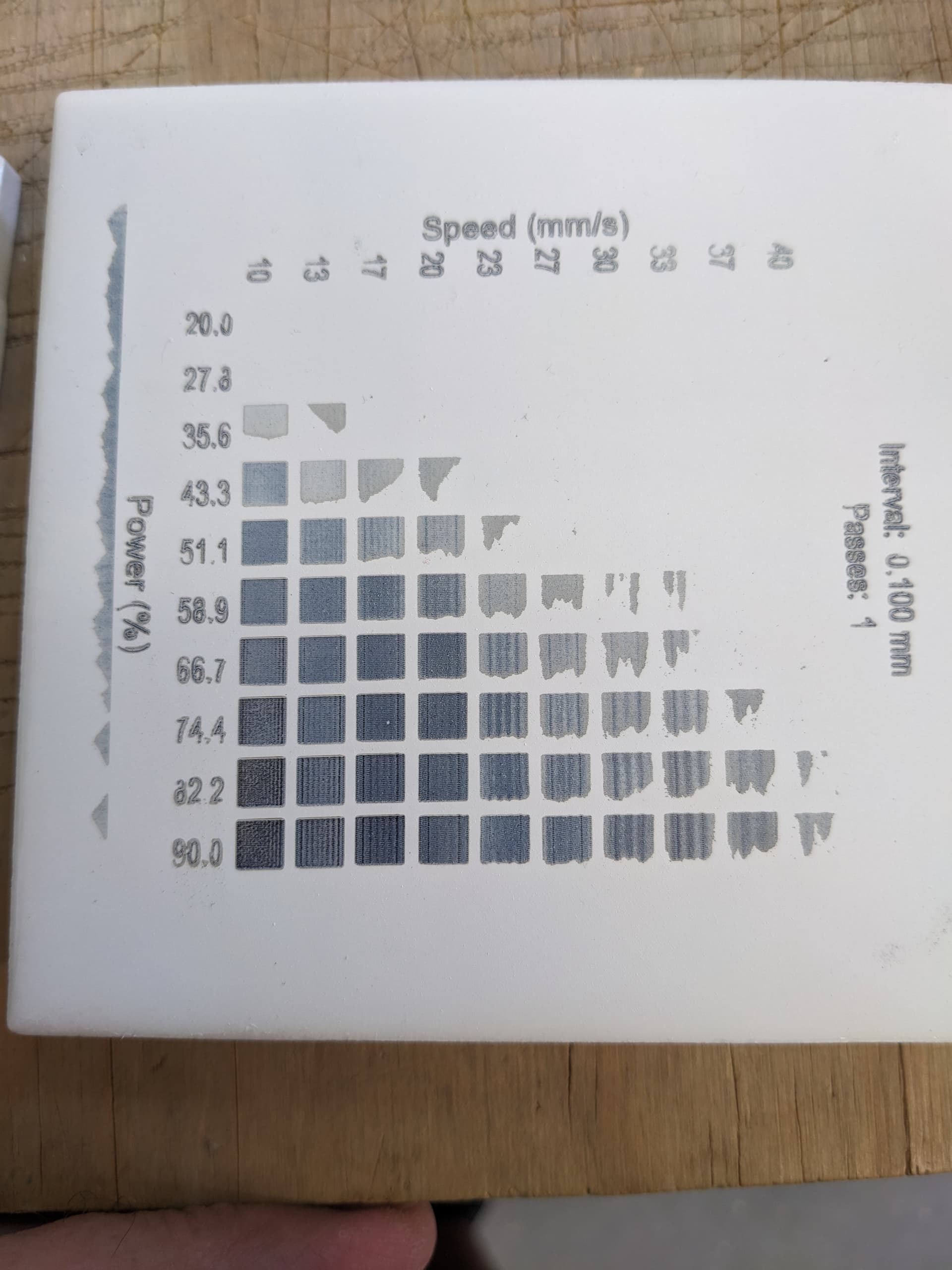
I used the material test to locate a good spot…
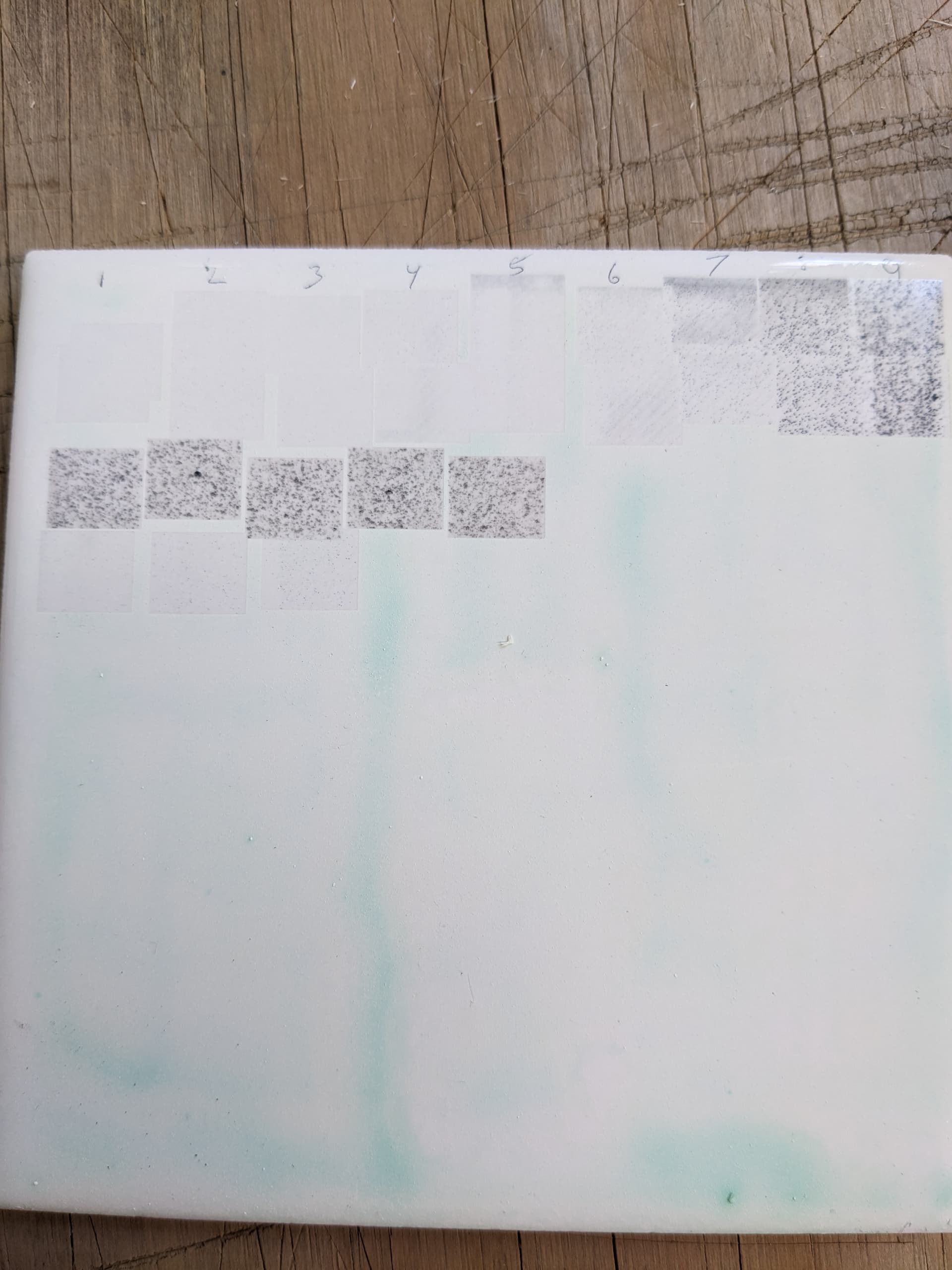
I did some tests today and it didn’t turn out so well. LightBurn can’t work with the ULS laser so it was very painful to run a square, move the square, go to manual settings, change the settings, repeat.
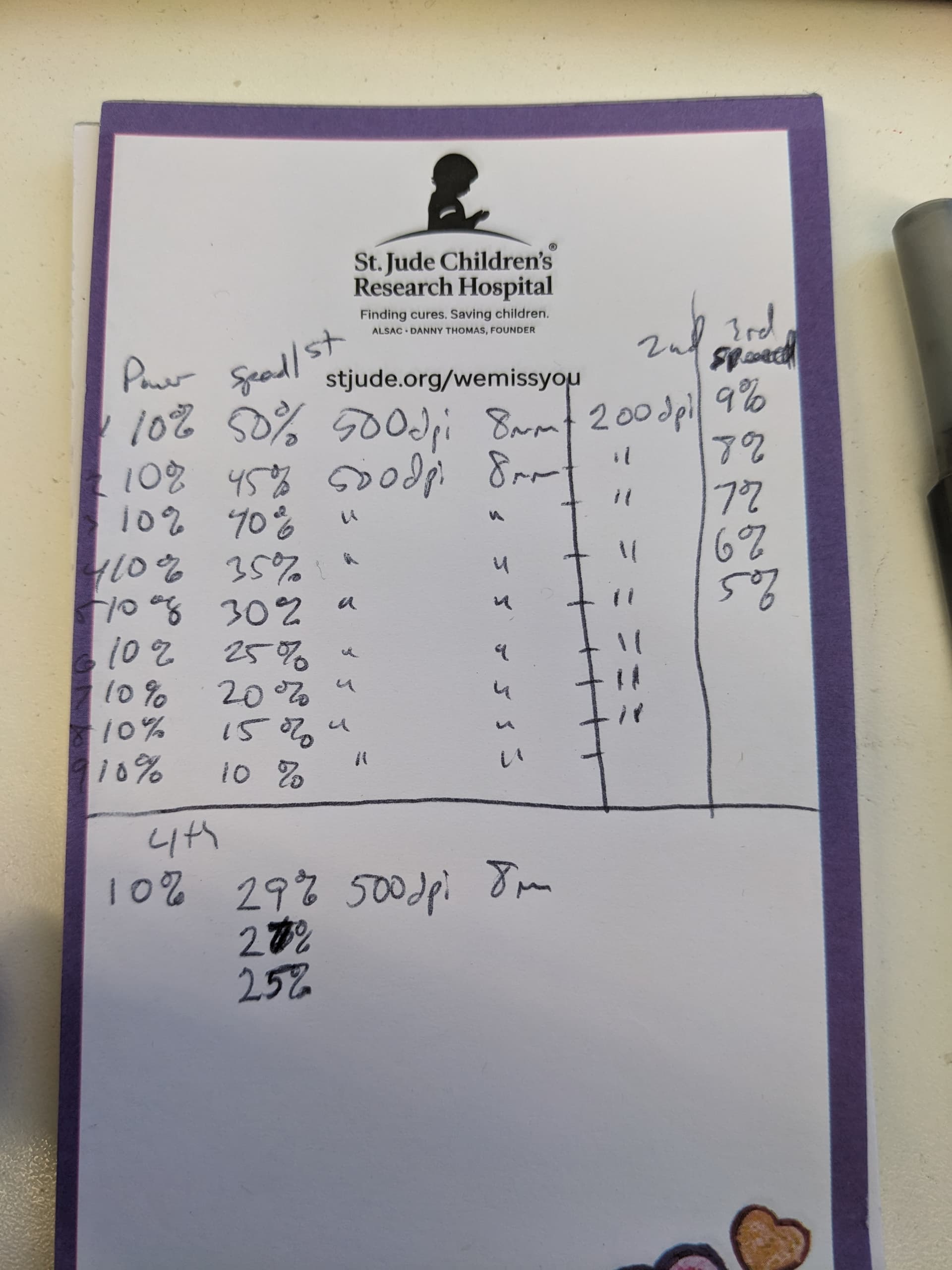
Each horizontal row is a test documented on the notepad. I ran one tile on my diode laser with LightBurn to validate the coating.
[quote=“jkwilborn, post:152, topic:38053”]
If you are at your power minimum, then your only options are to try a larger interval and/or go faster… [/quote]
This is what I’ve never seen anyone else actually figure out- you DO have an option. The HVDC excited tube should never be run at 10KHz-20KHz PWM freq, that’s absurdly wrong for these tubes. They have a 1ms response time, why is this being used??
The min power prob is actually because of a min pulse width, I’ve seen it around 150us. Reduce the PWM and you can get stable power at much lower levels.
The trouble is the controller at that point. Ruida’s PWM timer is free-running and will not be reset by what the content needs it to be doing. That is, if you turn the PWM to 300Hz, you can get lower power output at very low PWM duties. But when it encounters a pixel in a raster and should go from “off” to “on”, it won’t actually be able to change that until the next PWM cycled starts. And in the same way, when the laser passes the point where the beam should go off, it will have to wait for the PWM timer to reset first.
The Ruida’s PWM timer does not even reset at the start of a raster line, so the exact start and stop points shift on a per-line basis.
I’m not sure how other controllers work. Logically, it would do much better if it just restarted the PWM timer at the start of a pixel and stopped it at the end.
The power supply demodulates the 20 kHz PWM to the same baseband signal as the analog output would produce. The demodulation filter has a cutoff around 250 Hz, so any PWM “carrier” above a few kHz produces pretty much the same output: the input PWM signal doesn’t make it to the laser tube.
I ran some experiments a while ago, with this post summarizing the PWM results:
The controller’s analog output:
It looks like the KT322N controller in my OMTech laser has an internal lowpass filter demodulating its PWM output to produce the analog output, rather than an actual DAC, because the frequency response drops off much faster:
The results near the 250 Hz cutoff are anything but stable. Here’s what it looks like at 500 Hz:

The cyan trace is the PWM input to the power supply and the green trace is the tube current at 10 mA/div.
With the PWM carrier at 100 Hz, the tube current is basically following the pulses as though they were analog inputs, with rise & fall times kinda-sorta matching the 1 ms “spec”:

Bottom line: the PWM signal gets demodulated, so any details of the PWM carrier don’t matter.
Your RF laser is not the same as these glass tube lasers. The response time is based on the time laser enable goes active and the lps reaches >90% voltage.
The pwm doesn’t change during a normal layer… not including a grayscale… So pwm is present at all times a layer is executing.
PWM frequency on a dc machine doesn’t matter, as it can also be an analog control voltage, as @ednisley advised…
Whereas, with an RF machine, you can change your pwm frequency for advantages in certain circumstances, it doesn’t matter with a co2.
On a RF machine is a digital device and operates like a diode. All circuits have inherent delays…
I did physical testing on this. We’re not using analog to the hvlps on our hvdc machine. Pwm is more accurate IMHO.
What you can do is put paper across the machine bed, set up a job of a single line at 1000mm/s 50% power in a long straight line so it will have enough room to get up to the commanded speed.
Try overriding pen to different freq. At 0.1kHz, the spatial period of the pwm is 10mm so you will see roughly 5mm on 5mm off dashes.
Play with the period. At like 1kHz, the pwm is 1mm, still much larger than the focal spot so you should see 0.5mm dashes burned with 0.5mm gaps. But the edges be very blurry and it doesn’t actually have totally unburned gaps, just less burned parts.
That’s because there is an inherent delay from when the lps gets the FIRE command and when beam output energy hits its full wattage.
Here’s the big important thing: as long as the spatial period of the pwm (mm/sec divided by hz) is similar or smaller than the focal spot size, the cut or engraving will not show the change in beam power due to the slow pwm.
So, if you are going slow at 40mm/s and set the pwm period to 0.2khz, the beam power will rise and fall within a pwm cycle but may not show up in the cut. Depends on your spot size though- which depends on lens focal length, beam diameter on the input to the lens, lens type, and the power level and material cut. 0.2mm spot size is on the larger side for a 2" lens.
But whereas the beam might have a 15% min power at 10KHz (15ns on time pulses needed to get any beam output), at 0.2 KHz you can scale all the way down to 0.3% power and still get scaled average laser energy out of the hvdc exciter tube since that’s the same 15ns on-time.
AFAIK most of this limitation comes from the flyback transformer in the lps rather than the tube itself. It has a diode and capacitor on the output and that requires a finite amount of time to charge. I think it’s asymmetrical too in that the lps doesn’t discharge that cap directly, the tube drains it down so turn off period may be slower than turn on.
So, I tried the tio2 with school glue and water. one-part tio2, one part glue, two parts water It virtually left no mark on the tile. I then doubled the amount of tio2 with little to no difference. I then sprayed tile with white paint and same power/speed settings and got good results.
Seems to me tio2 is tio2. maybe I should have this white powder tested. Or maybe install some cameras to let me know if feds or cartel are coming for me.
You might to better using weight measurements instead of volume. Works ok with liquids, but isn’t very accurate with dry material.
Most chefs use weight over volume for dry materials, it’s inherently more accurate.
After several very messy previous attempts at using TiO2 powder, I saw this video and followed his directions to the letter.

His recipe consists of…
3 parts water
1 part Elmers Glue
1 part TiO2 powder
A few drops of food coloring to tint the mix
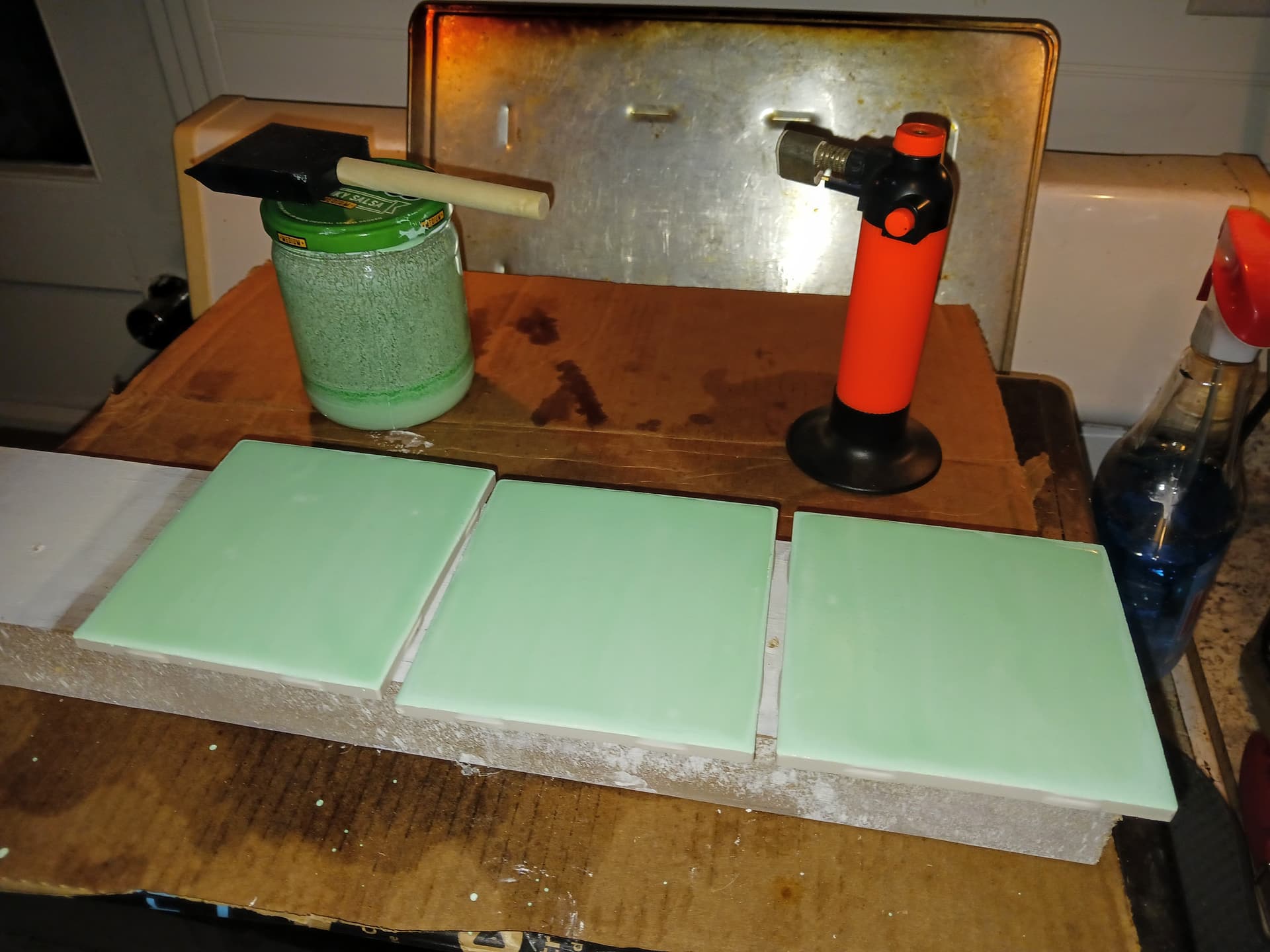
and is lightly applied with a foam brush. I used a small propane torch to pop any bubbles instantaneously!
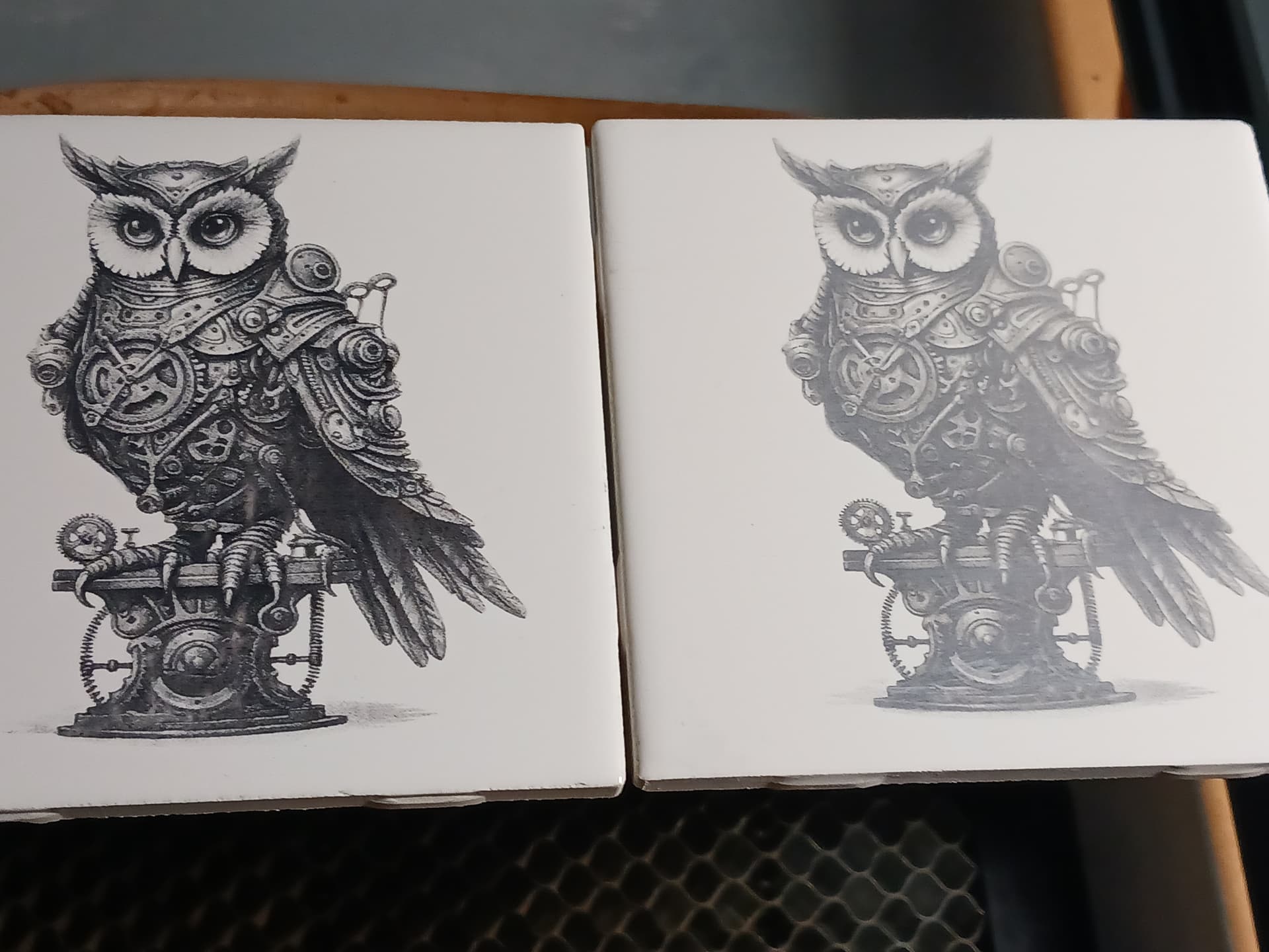
I had far better results than the NWT spray paint methods I started with… way less messy, darker, and at faster speeds with a 5W laser vs 2.5W laser I had always used previously. TiO2 on the left, flat-white spray paint on the right.
The author uses a 10 watt diode laser and in comments section says… “10 watts and I only needed 45% power at 5000 mm/m”. IIRC I used something like 3500 mm/min and 90% or 100% power with my 5W laser… determined by doing a test tile.
YMMV.
– David