New Ruida rdc6332 laser build everything works manually, but no fire / Movement through lightburn

Hey all! This is like the 150th Large laser I’ve built, but it’s the first time I’ve run into this.

I can manually fire the laser from the ruida
I can frame, Trace, home, manually move the head all over the table, but when I run a cut file, The head moves to the origin point, and neither moves, nor fires… It just sits there for however long it takes the file to cut, then “finishes”, and beeps that it’s done.

I’m not getting any error messages, Water protect is de-activated, no interlock, Like I said, the machine thinks it’s cutting, but it’s not!

I’m almost inclined to believe there is some sort of “enable” signal I’m supposed to be sending it. I took pictures of the machine I tore down for the parts, but I seem to have taken every single photo so that I can’t see the CN2 port.

Anyone have any ideas as to why things are not enabling when I run the file?

Thanks so much!

If you can fire it from the Ruida control panel, I would think it would be a happy camper.

What is the most suspicious is that it doesn’t move. If all but the laser was right, then it would follow it’s ‘course’ laser or not.

I think it’s something related to both.

The only place I can think of is in the vendor settings for the laser enable for tube 1 or 2.

Here’s a picture of mine, with the CN2… what are you looking for there?

:smile_cat:

CN2 Pin 2 is a “Special Input” the manual is chinglish as hell, but from what I gather, this port may be almost like a machine interlock, which I may also need to connect to the relay I’m using for compressor air / nitrogen solenoid.

I’m almost certain that I needed a jumper, or relay to enable movement / laser.

I just haven’t used one of these controllers for a couple years.

I don’t see your photo. If you wouldn’t mind, could you try to post it again?

The machine is in fact happy… that’s the weird thing… I’ve had a similar issue in the past, but cannot for the life of me remember what it was.

I found this version of the manual and I’m not clear on the ‘special input’ you describe.

They claim that CN2 is an output connector. From what I can see, OUT2 is the same as ‘Status’ on mine and will sink when the machine is executing… do you read it that way?

Here is CN5 has L-IN3, but they don’t really state it’s use.

:smile_cat:

Yeah, that’s what mine reads. I can usually use the CN2 out 2 for relay trigger.
I’m going to re-check all of my Ferrules on the power supply side.
reading the laser power supply manual, I think it reports back to the controller that it’s in a “ready” state. I can’t remember where it came from, but I have a jumper here from the teardown.
it’s gonna be a long night…

If it was disabled via a jumper, I don’t think the Ruida would let you fire it from the console. Mine will choke if any of the safeties are not ‘active’ when I try to pulse it.

Can you post a photo of the wiring for us to look at? The lps and your controller. The manual photo of the controller is so bad I can’t really read all of the pin functions, at least on the photo.

:smile_cat:

Yes, that was my next question actually… Are you familiar with the MYJG-100 style power supply? I’m running it with low signal, ground, and control. The other 2 blue and red wires are water protection, which I disabled in the Ruida, as The chiller has a really nice built-in protect system.

Here’s another twist… It will not run a file successfully with RDworks either, however, If I run the framing command in RD Works, where it frames, and cuts at the same time ( they call it trace or something like that) it will laser the boundary, but not the cut design…

I tried a second computer, no luck! The control signal light on the power supply does not light up when a file runs. so it’s firing fine via the keypad, but I went through each and every setting, There are no alarms, or i/o ports triggered.

I feel like there used to be a wire from the power supply to the ruida, originating at the 5v output on the extreme right hand side of the LPS, but I just don’t remember.

Mine is an mYJG60w

How does your chiller tell the machine it’s working?

Where do you have it wired?

On mine

Ruida lps
L-ON1 → L
LPWM1 → IN

P & G are strapped to ground.

:smile_cat:

OK, I’m sorry about the photos, I have to get back to my shop…
here is one thing I’m wondering about… You know the led indicators down the right side of the controller?
#1 which is +5V indicator, is on solid. I cannot figure out if it’s supposed to be off? I’m thinking that may be where the 5v from the laser power supply comes into play. I may be completely off, but that seems to be the only indicator anywhere throwing up a flag.

The #2 led which is labeled “Run” is constantly flashing off, then on, about every 2 seconds. It goes out for about 4 seconds when the file completes, and the controller does it’s little beep beep thing to let you know it’s done…

Does your controller have the same lights lit?
Thanks so much for the second set of eyes.

By the way, You’ll notice i’m in the “High” position on the LPS… I switched it in the software as well for testing… I’m back to low now. WE are wired exactly the same…
Here’s My controller

CN 0 goes to keypad
CN 1 goes to 24V power supply
CN 2 Pin 6 and Pin 1 go to the inductive limit switches the blue and red go to my compressor solenoid relay
CN 3 is blank
CN 4 are the 2 NPN leads for the X and Y limits
XYZ are self explanatory
CN 5 is power for the 2 red dot lasers
CN 6 Pin 6 goes to “IN” on LPS Pin 3 goes to “Low” input on LPS Pin 1 goes to GND.

This was wired this way previously… I would not have put the colors in those positions… lol

I have a 5000 ft. roll of shielded & grounded CNC wire I’m going to replace these with once I get it working. I didn’t want to go Yanking all of these cables out yet, until I had My I/O map documented properly.

Thanks for the photos.

Should not CN3 pin 3 go to L on the lps? It looks like that’s the L-ON1+, I’d think it should be the L-ON1- or pin 2.? L needs to go low for active.


You’re using the analog, I used the LPWM1+ for the IN of the lps… don’t think it should matter.

:smile_cat:

Yes, Good eyes… as I stated above, I had had the cables switched to high input just to test. Everything is moved back to low… I will try the PWM output. I had understood from cloudray that the power supply was digital, but when I wrote them, asking where I could get a manual, or at least a slightly more detailed explanation of the I/O scheme, as all I really wanted to know, is what the 5v was for. They say it’s 5V input, but it’s clearly putting out 5V.
I asked if they have a PDF manual, so I can put it in the binder of manuals for the customer who owns this machine… Their response was “Why would you need a manual? It’s a power supply! There is no manual” I think Cloudray just took their glove off, and slapped me across the face! :laughing:

Touche’ Cloudray!

There isn’t much on lps. You can find schematics of them, but I don’t know how well they relate to what’s really there. Every one I’ve seen with a +5v pin, is a 5v supply limited to under 200mA, maybe less.

On my machine, it lases when L-ON1 (-> ‘L’ on the lps) goes low. If you have a pwm and L goes low it should be firing. You can check your pwm with the voltmeter.

If you have a voltmeter it should be relatively easy to check. I don’t think the lps even needs to be operating at least to check it out.

I’m guessing that L-ON1 isn’t going low when it’s operating.

:smile_cat:

OK, just to catch up… I am wired and configured exactly the same as you. I switched to LPWM1+ which is running to “in”
L-ON1- is running to “L”
GND to GND
I’m also using WP1 instead of the chiller’s water protect… either way, that’s always been working.

I understand how it works when it goes low.

I’ve just decided to tear out all of the old wiring for at least the laser circuit, and swap out for proper shielded CNC cable.

Here’s the really weird thing… L-ON1- Stays Low the entire time…

I decided to switch to the PWM channels.

Are you running PWM+, or PWM -? You never stated which one…

If I hook up to PWM-, the laser fires non-stop. If I hook up to PWM+, the laser shuts off, but It never fires.
At this point I’m fairly sure that a pin got smoked.
I’ve re-configured 15 times from scratch, re-wired, and re-drew My diagram.

On my machine the laser fires when L-ON1 goes low. So it it’s ‘stuck’ low you need to find out why. I wonder how your machine deals with some things. You state you change the polarity of the signals via the console, but the controller has what appears to be inverted outputs…

I think… these are the L-ON1/2. Mine is set for going low to be active.

Screenshot from 2022-06-03 17-53-16

I don’t have that option, as you can see.

Chase down the issue with L-ON1 being low all the time. I’d check the controller first…

Do you have a voltmeter? See if that output even toggles. Shouldn’t need the lps to check it out.

Good luck

:smile_cat:

Yes, I have been working with my big bench meter on the far end of the machine near the LPS so I can see it, and I have meters hooked up to a couple other outputs, so I can see immediately what if anything changes.

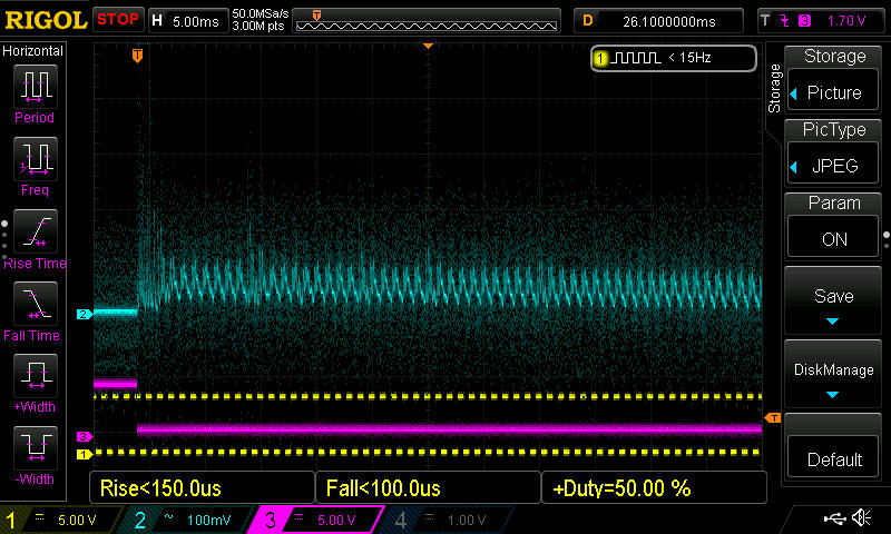
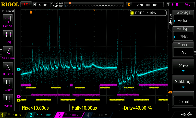
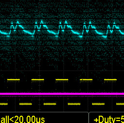
Looking at the pwm at different power levels, it’s a bit dirty looking. (Noisy)

that’s why I re-wired everything, and bonded the shields.

I definitely have the various parts of the recipe, but I think perhaps when I was exhausted, and just kind of trying everything (even things I know will not necessarily work).

It’s all kind of a new learning experience, as I’ve literally assembled well over 50 or more multi-head laser tables, and they always just work.
So this is a new troubleshooting experience.

I wasn’t really sure how it all talks to each other.

I’m still not positive.

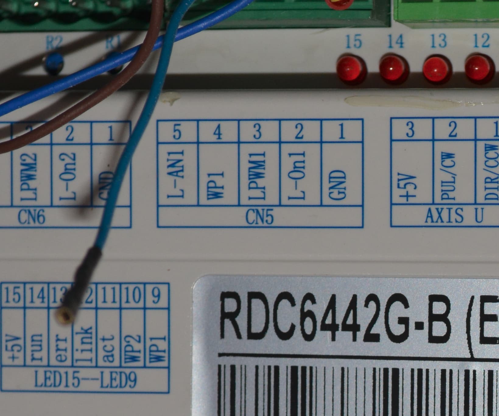
using the oscilloscope, I’m making an educated guess that the software tells the control board to go low on that pin. The LPS is always sending the voltage to the controller. The controller bridges that incoming power, almost like a relay, and then the power supply itself goes “active”. At that point, the modulated signal tells the power supply to fire, and at what power level.

I’m only following the clues based on how this board is currently behaving. If it’s malfunctioning, then what I’m seeing is not the way it should be working.

I have a new RDC 6445 showing up tomorrow from Amazon.

I have one of those little Ruida 2 axis mini controllers I use on the bench for testing, and it seems to move x, Y, and fire laser.

I’ll open up the 6332 after I swap, and try to diagnose.
like I said, I was fiddling, and didn’t use a pull-up resistor. It’s entirely possible that I damaged the chip.

I know better, but sometimes when you’re frustrated, and tired, you don’t think it through all the way.

Thanks for keeping me company.

Whether I was a dumbass, or whether the controller or even power supply went bad, I will hopefully have the thrilling conclusion to this story tomorrow. And I’ll own up to any mistakes if it comes to that.

Which software…? the ‘code’ that tells the Ruida what to do is sent to and stored on the Ruida. On a K40 type, that’s not supported by Lightburn, the control board is told by the PC what to do and cannot run without the PC attached.

The controller only tells things what to do. It doesn’t control the power per se, it only has digital (ttl) control over the lps/motors and such.

What tells it to fire on my Ruida is the L-ON1 signal, when it goes low. My ‘modulated signal’ (PWM) runs continuously while the layer executes. Lasing or not.

Not sure I follow. The lps has no signal wires back to the controller.

I doubt this is the issue, but how is this wired. You mentioned you used the chiller protection, how is it wired?

I haven’t built a bunch of these but that Chinese wiring doesn’t have any ‘shielded’ wiring in it and it runs fine. I think a ‘rewire’ from that angle a waste of time and you will be in the same boat after doing so. It will also induce errors, just what you don’t need. You need to settle down and fix what we know is broken.

We know the L-ON1 must not be low all the time.

Did you check your Ruida to see how the ‘Laser 1 output signal’ is set?

Don’t work when you are tired or frustrated… probably what caused this in the first place :crazy_face:

Find out why L-ON1 is always low. I use this as a trigger for my scope…

:smile_cat:

Alrighty man! As it turns out, the controller was indeed smoked. There was voltage bleed on everything. I really don’t know how it even ran manually. I swapped controllers, loaded the profile from the old controller, and everything ran smooth as butter.

To respond to your questions, I will say this:

You cleared up my misconception of the PWM’s purpose. I thought ON= “armed and ready” and the PWM controlled the output from 0 to 100%. Now I see that the PWM is essentially just the “potentiometer” which sets the power output, and is constant.

I realize now there is no signal from the power supply. I just meant there was constant voltage (that I thought was coming from the power supply, I thought that was to let the controller know it was ready, but as it turns out, it was coming from the controller. Because it was erratic, I really had a hard time pin pointing what was what.
With the new controller, it was very simple to tell that it was stable, as I didn’t have stray voltage creeping in on every single pin on the I/O side. It wasn’t that it was going low, it simply had voltage bleed.

Thank you so much for taking the time to respond so thoroughly. Though it was a bit frustrating, it was also quite fun to take a deeper dive into the inner workings. And learn a bit more about how they work, as opposed to simply hooking things up, and patting myself on the back because everything functioned properly.

I need to dial in the steps, and raise the tube up about 5mm, but otherwise, she’s humming now! I tried to upload a nice video, but it won’t let me.

Great that it’s up. I had lots of misconceptions myself and when I hung a scope on the Ruida, things just didn’t make sense. I still have questions about a few things…

Here is the scope trace for you to see

Top line is the voltage across the mA meter. Purple is L on the lps or L-ON1 from the Ruida, it is also used to trigger the scope. The yellow is the pwm from the Ruida. The pwm period is set to 1mS (1kHz) at 50%.

There is no voltage before L-ON1 goes low, but the pwm is constant. There appears to be no ‘synchronizing’ of the L-ON1 to the pwm ‘on’. I can understand that, not any real reason for it.

This one the pwm is 40%, and the L-ON1 signal is changing states…

This is ‘zoomed’ in and you can see the pwm state has some effect on the mA voltage.

DS1Z_QuickPrint3

Isn’t how I imagined :crazy_face:


If you wish to post a video, you can put it somewhere like google drive and post the link.

Glad you’re up… take care

Have fun

:smile_cat: