I recently built a MPCNC and added a laser module (Banggood 3.5w diode). It’s using a RAMPS board (actually a MKS Gen L) running Marlin 2.0. I come from the world of 3D printing, but I’m new to CNC and Lasers. I’ve been playing with various software tools and just found LightBurn. It is by far my favorite so far. I’m still on the trial, but I will likely buy it. I do have a few questions, some of which I was able to find the answer to searching this forum.
How do I set the travel (non-cut) moves? Does the Speed setting in the Cut Settings Editor apply to both cut moves and travel moves? Or is there a way to set them independently? I’m getting dark edges which I think is because of the change in speed (acceleration/jerk) between cut and travel moves, but if they were set the same it should eliminate a lot of that.
Can I configure custom starting and ending gcode? I use an IOT relay wired to the extruder heater pins on the RAMPS (laser control is connected to the fan pin and controlled with M106/M107). My spindle or laser power is plugged in to this so I can turn them on and off with M104 gcode commands. In every other program I’ve tried so far, I’ve been able to customize the starting and ending gcode. My starting gcode sets the current position as 0 for all axes, turns on the spindle/laser power with M104 S200, then M107 for safety to make sure the laser is off, then a M0 S3 to pause 3 seconds to let everything fully power up and get to speed. This gcode works great for both the spindle and laser applications. I also like to use ending gcode of M400 to wait for the buffer to clear, then power off the spindle/laser with M104 S0.
While editing the gcode manually is certainly possible, it would be sort of a pain. Custom beginning/ending gcode is such a basic feature of every 3D printer slicer and laser gcode utility I’ve used so far, and LightBurn is such a feature-rich program that I think I must just be overlooking it somehow.
I think all of my other questions so far were answered by searching the forum. But I’m sure I’ll have more. Thanks!
You’re not overlooking anything - LightBurn doesn’t currently allow editing GCode, mostly as a way to prevent support issues, but also partly because LightBurn was designed for dedicated laser systems, then retrofit to support CNC use, and that process is still happening.
Travel move speed for Marlin controllers is the “Fast Whitespace” speed in the device settings. GRBL and Smoothie controllers have this in firmware, but because Marlin treats G0 moves as G1 moves it needs a setting for it.
Marlin is the least recommended controller type. It does not do power ramping, which is why the start/end points and sharp corners are burning. You can improve this by enabling overscan for images or fills, but there isn’t a way to fix it for vector marking.
For your start / end code, you could set them as macros for now. It is on my list to have pre/post job GCode editing, and that should happen before too long.
The tooltip for that setting explains it is the “minimum speed to scan over blank areas of the image.” How would I set a maximum speed?
I currently have “Fast Whitepace” disabled. My assumption would be that would make the travel move speed the same as the cut move speed. So with a black and white image (no grayscale) the scan speed would be consistent with the laser just turning on and off. Is that how the setting works?
I also do have overscanning turned on. How does the Fast Whitespace setting work with this? And does the overscanning only apply to the extreme edges or to internal gaps as well?
I’m not sure your question makes sense, based on how this works. If you set a scan to happen at 100mm/sec, and have Fast Whitespace to run at 200mm/sec, it’ll use the faster of the two speeds when scanning the gaps. If you ran a scan at 300mm/sec, but had Fast Whitespace set to 200mm/sec, it would use the 300mm/sec speed, because that’s faster.
With fast whitespace disabled, yes, it should all move at a single speed as you suggest.
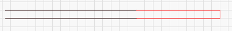
Overscan is an extra move added before a direction change to allow the laser room to decelerate after it stops firing, instead of while it’s still on. Overscan wouldn’t make sense for the moves in between, because the laser is just moving continuously there anyway.
In the image below, the red area is what overscan adds - it’s a move where the laser continues in the direction it was going already, but with the laser off. By letting the laser do the bulk of the deceleration and acceleration with the beam off, you don’t get extra power dumped at the edges of your image. This is normally handled by power ramping (lower the power as the head slows down) but not all systems support that, and laser power isn’t linear anyway, so this is more reliable.