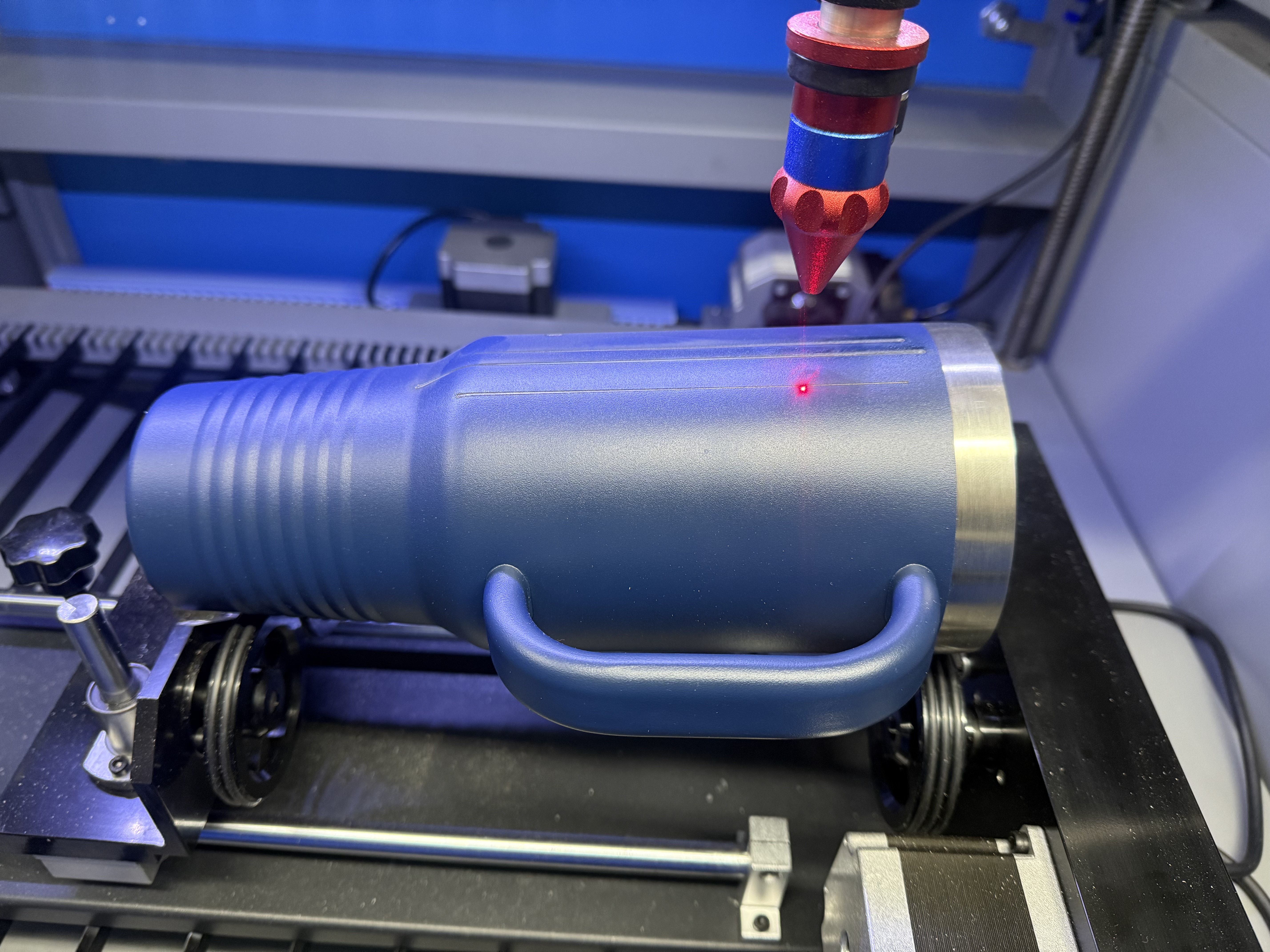
I bought this 60w omtech laser at the end of 2024 for my printshop. We’ve been busy so I haven’t had as much time as I’d like to dedicate to it.
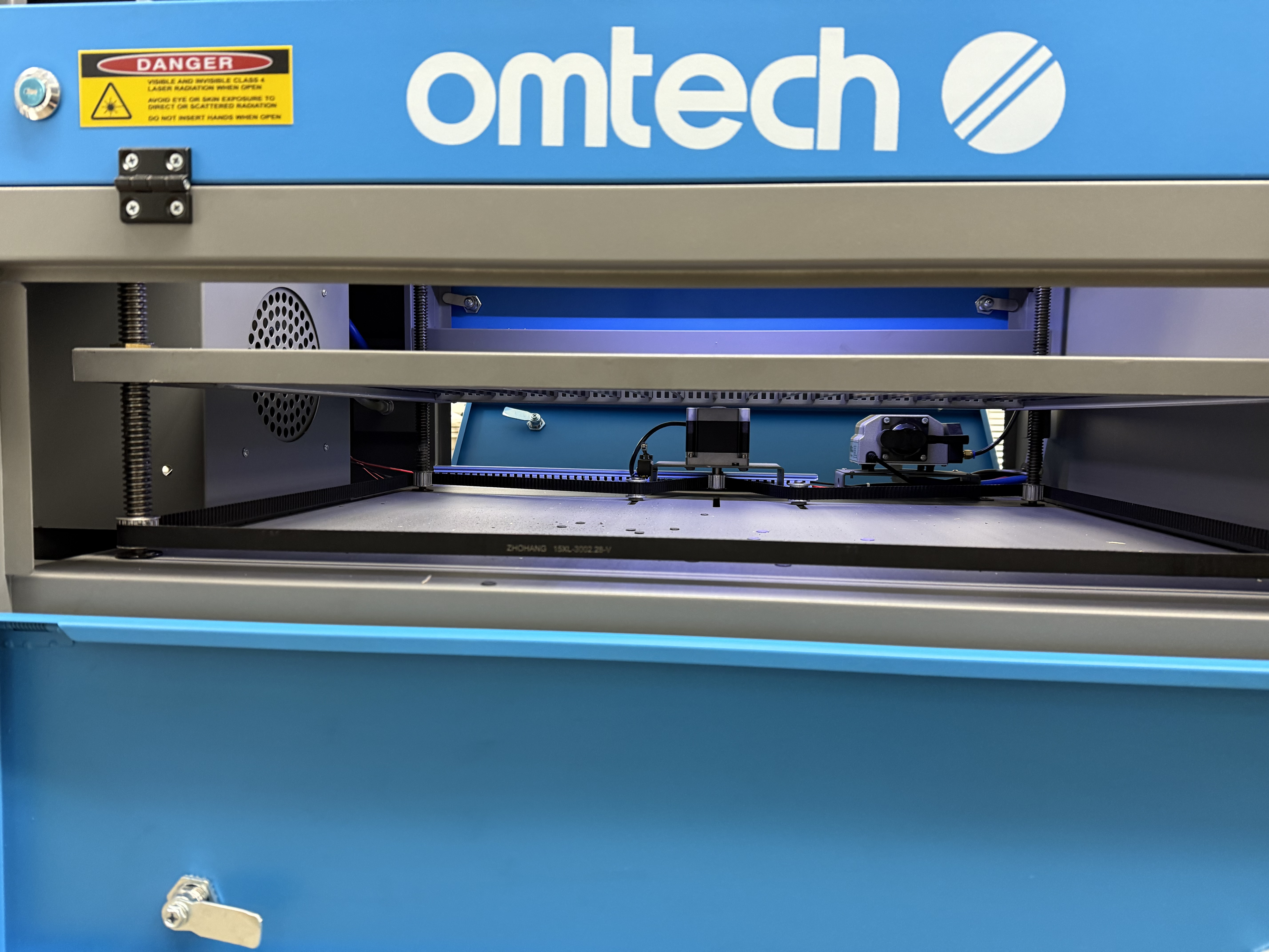
I recently purchased a rotary (I called and it’s the model omtech said I should buy), but in trying to set it up I don’t seem to be able to get the auto focus bed low enough. I’ve even removed the feet of the rotary device and the honeycomb.
I have 2 questions:
It seems like my bed should go about 6” lower, but it bottoms out at this height. Does this seem right or should it indeed go lower? Any advice on how to accomplish that?
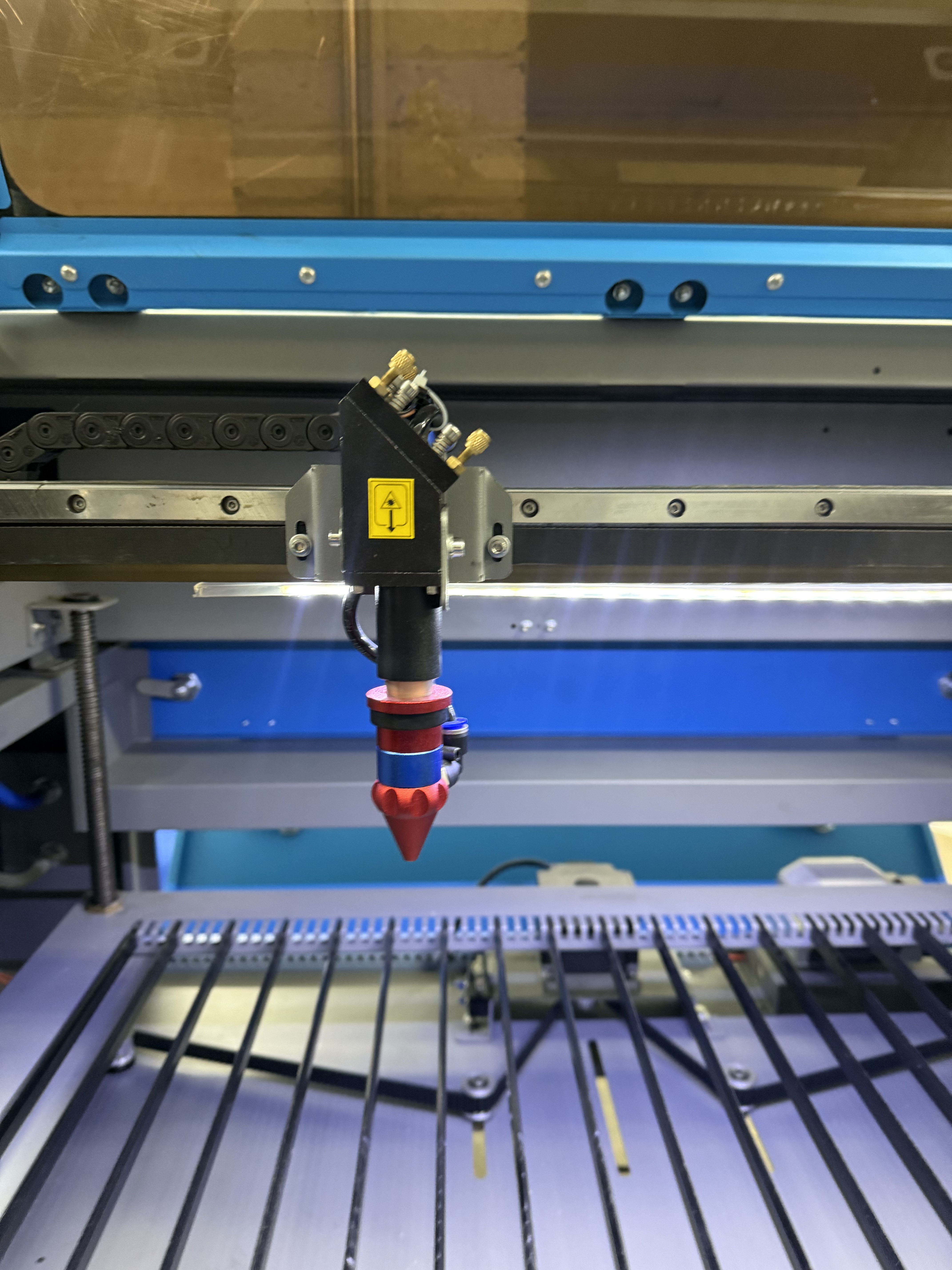
It seems like my nozzle is very long, is there anything I can do to raise it? Like I said I’m very new but Im a tinkerer and own lots of complicated machinery for my business that I maintain and fix n a regular basic. Any guidance on how to accomplish this would be highly appreciated.
What you’re seeing is the default controller behavior.
The axis running the platform motor (either Z or U, depending on the controller) has a preset maximum travel distance relative to the home position. Before you home the axis, the home position is wherever the platform was when the controller started up. When you hit the Focus button, the home position is where the platform stops.
Ruida controller do not allow moving the platform upward beyond the home position, but you can move it downward to the limit set by the maximum axis travel. That limit is small enough to prevent the machinery from crashing into the stepper motor / air pump / pulleys / other widgetry screwed into the cabinet, but may not cover the entire range of motion.
Here’s the trick: if you lower the platform as far as it will go, then reset / power cycle the controller, that position becomes the new home position and you can lower the platform from there. Because the physical limit is less than twice the maximum travel limit, you’re now free to smash the platform into all the stuff down there.
You can change the maximum distance in Edit → Machine Settings. If you measure the actual distance from the normal focus position down to let the rotary fit under the nozzle, setting that value will let you jog the platform to where you need it.
Thank you for the detailed response I truly appreciate it!
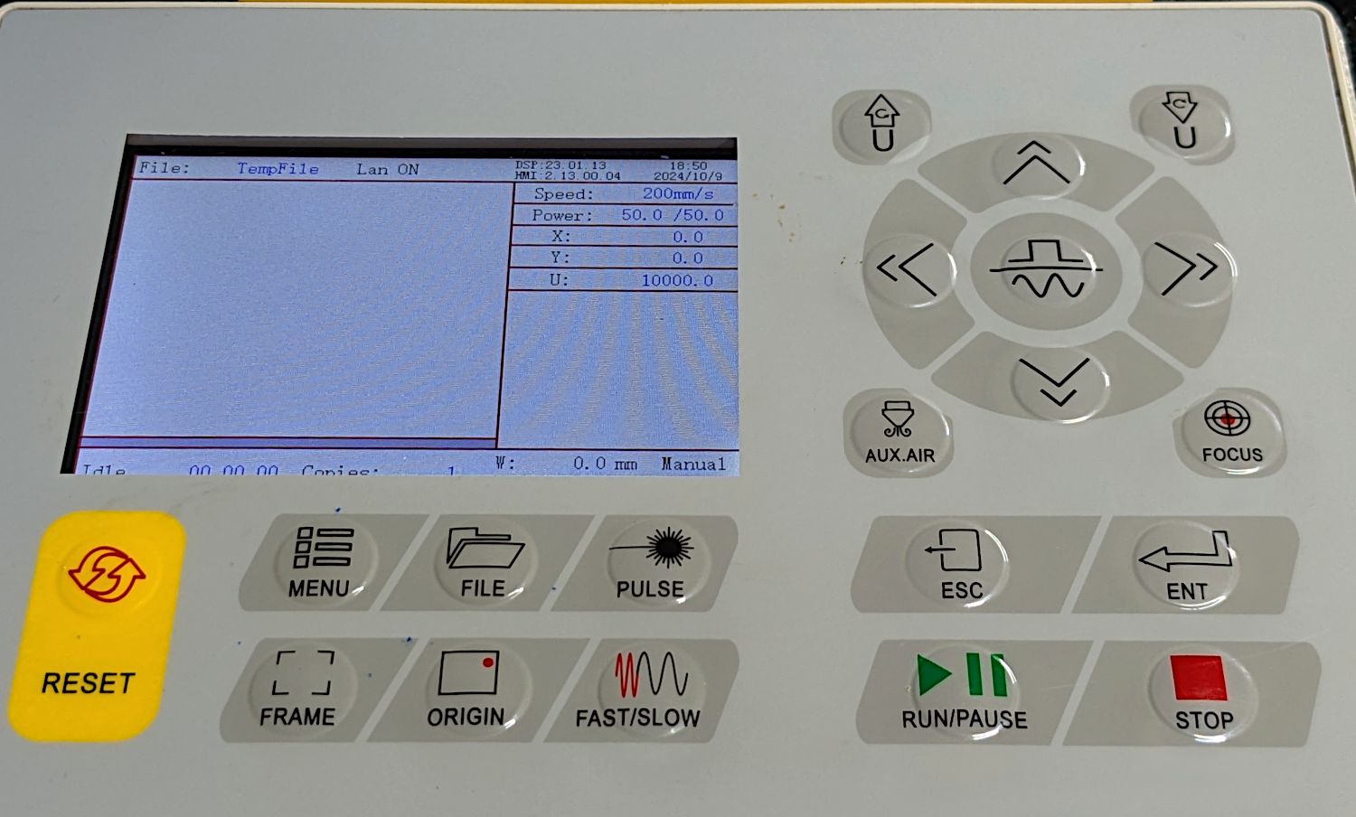
You seem like you know WTH you’re doing..,when I use the arrow keys on my laser itself to direct the x/y position…it moves so damn fast I can’t do anything precisely…is there a way I can slow it down?
My KT332N has a button in the middle of the jog arrow buttons selecting either Continue or Manual jog mode: the former moves as long as I hold an arrow button down, the latter moves one fixed-size step at a time for each button push.
It also has a Fast/Slow button that I hold down in addition to an arrow button for high speed jogging.
How you set that up depends on which Ruida controller you have, but I hit the Menu button, then:
Para Set → Speed Setting → “Manual” fast & slow speeds (I have 500 and 100 mm/s)
Manual Set → 0.2 mm step size
Laser Set → “Laser” mode, 40 ms pulse
If you don’t already have the doc for your controller, your favorite search engine will help. However, the verbiage isn’t particularly informative and typically does not exactly match the controller on your machine, so some reading of the tea leaves is required.
Hang out around here long enough and you’ll see everything march past …
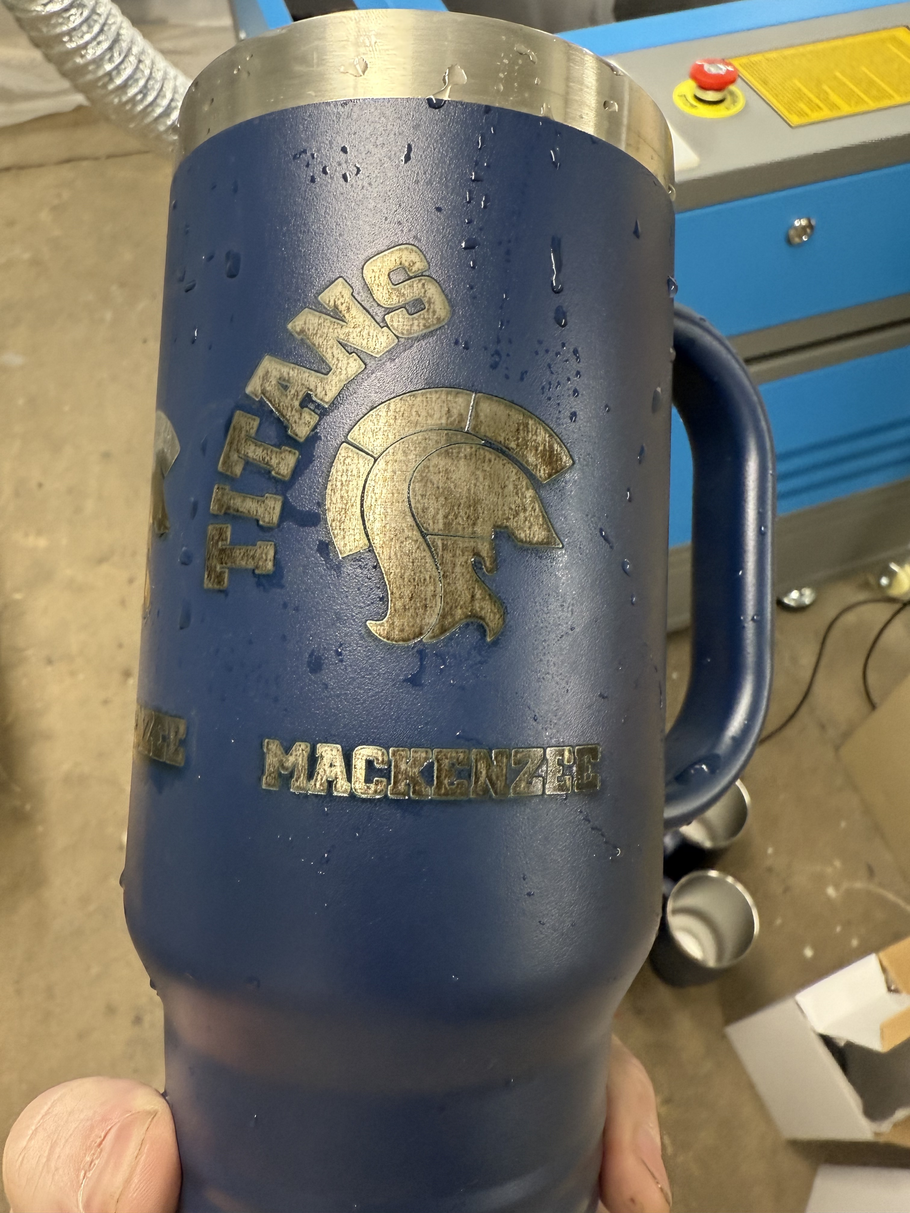
I’ve been learning all day. I just realized I had my nozzle was way too close (3mm) and I’m slowly backing it off and the engraving is becoming much more focused / sharp. I’m at 15mm currently
Here is what it looked like at 3mm (it slipped on the rotary)
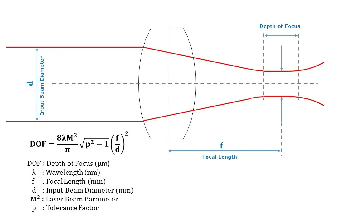
The lens focuses the beam to a narrow waist, about 0.2 mm diameter and a few millimeters tall. The ramp test tells you where the middle of the waist sits and you want that point on the surface of the material.
Deep cutting might call for putting the middle of the waist a millimeter or two down into the material, but that’s about it.
So I just slanted my new rotary downward and designed a straight line to cut down ward toward the base. If I measure the height where the line is the thinnest, that would be my focucal point right?
You can measure it on paper, rather than a mug, because it’s a property of the machine, not the material.
The speed & power level depend on the material, so that’s why you must run Material Tests on the real thing.
Verily, it is written: “One careful measurement outweighs a thousand opinions.”
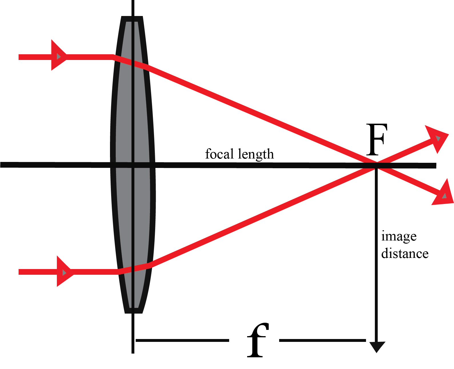
The focal length of the lens determines the distance between (about) the middle of the lens and the center of the focused waist, but you can only measure between the nozzle and the material.
Your machine is your machine, with its own components and settings. Therefore, your measurements will tell you what it’s doing and my measurements (or anyone else’s) are only a guide.
Assuming the rotary is plugged in (thus replacing the Y axis), then you must also limit the Y axis speeds & accelerations so the mug doesn’t slip on the rollers.
Protip: Alwayssave a copy of the Machine Settings before screwing around in there.
Bonus: Save the settings you have now as a file named “Linear” and the settings for the rotary as a file named “Rotary”. Then you can switch between them easily and completely every time.
Oh wow great tip. I found these settings earlier, but didn’t realize I could expand the vendor settings.
I was really struggling with when I would “frame” my design, the y axis would go flying off and spin the cup. I did figure out how to slow the y axis generally but there seemed to be exceptions as to when it would follow that slowdown. Hopefully this resolves them all
I went back to my laser today and converted it back for “flats” instead of rotary, I loaded my saved settings (I made a backup like you told me to) and made sure I’m not in “rotary mode”
However now when try to burn something, my design is pinched on the y axis, it’s not as tall as it should be
There are on-line calculators for computing much of this information.
If you know the focal length of the supplied lens, you could measure from the approximate center of the lens to the mug.
If you want to test on mugs, which is too expensive for me, but I’ve wrapped my expensive object in masking tape and marked it to ensure I’ve got a good image in the right place. Peel off the masking tape and adjust power for the finished product.
Be certain you don’t have the rotary enabled, because it’s very easy to be mistaken.
Take a look in the Machine Settings for the X and Y axis distance/step values: on a CO₂ machine, they should be equal. If not, then the settings you saved as Linear have values from just after you started fiddling around to set up the Rotary.
You can load an auto-saved config backup from long before you did all this, which should reset everything to the linear-only status quo ante.