Machine- TTS-10 Pro
Lightburn- 2.0.04
Computer- Early 2015 13" MacBook Pro running Monterey OS 12.7.6
I have been using my machine for about a year to mainly cut words and shapes from 5mm MDF (10mm/sec, 90% power and 13 passes) as well as making toys & figures from1.5mm plywood (20mm/s, 70%, 4 passes) and layered bowls, gears etc from 6mm plywood (10mm/s, 85%, 16 passes). Unfortunately I have not got a air pump yet so always deselect the air option.
The focus is always adjusted to suit the thickness of the material being cut.
Recently, however, these settings are not working and I haven’t been getting a complete cut. eg. the 1.5mm ply would not completely cut through at 100% power and 10 passes so I cut the speed by half and still had to physically break some of the objects out of the material. When I tried the 5mm MDF even over 40 passes with the original settings only resulted in a 75% penetration cut of the board. Even engraved reference Target Position marks at 40mm/s at 50% are barely visible now. Lightburn has recently been updated but this problem started occurring before the update.
I have…
… always kept the lens clean with disposible isopropyl spectacles cloths. There’s no visible defect on the lens.
… checked to ensure the S-value max is set to 1000.
… projected the laser at a wall 1 metre away and it shows a nicely defined rectangle.
… rebooted the computer.
I am now desperate for ideas as it’s driving me insane. Could the laser module be failing… how do I check it?
MikeyH, Many thanks for your suggestion, although the laser module wasn’t gunked up your help wouldn’t have lead to this discovery.
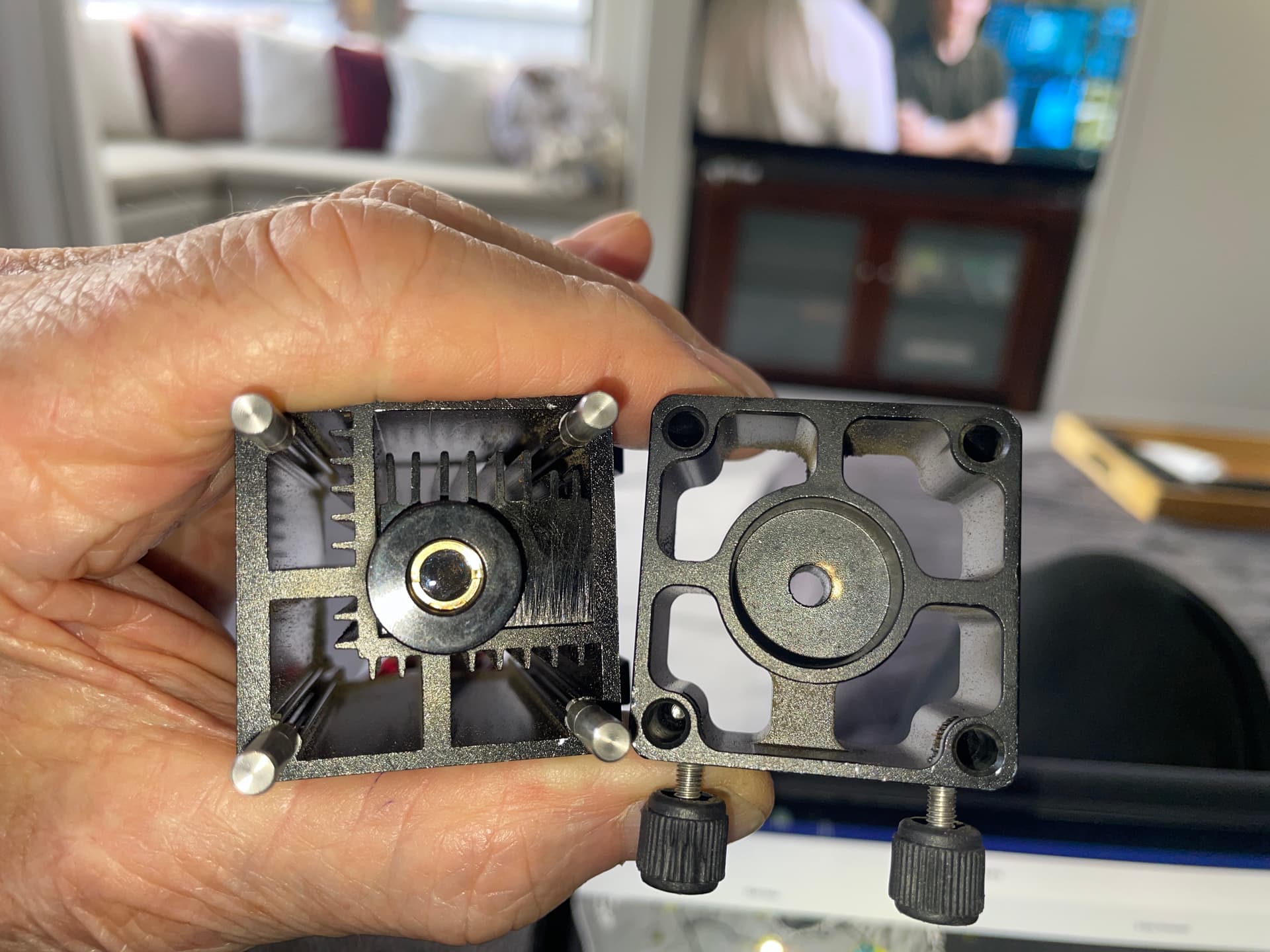
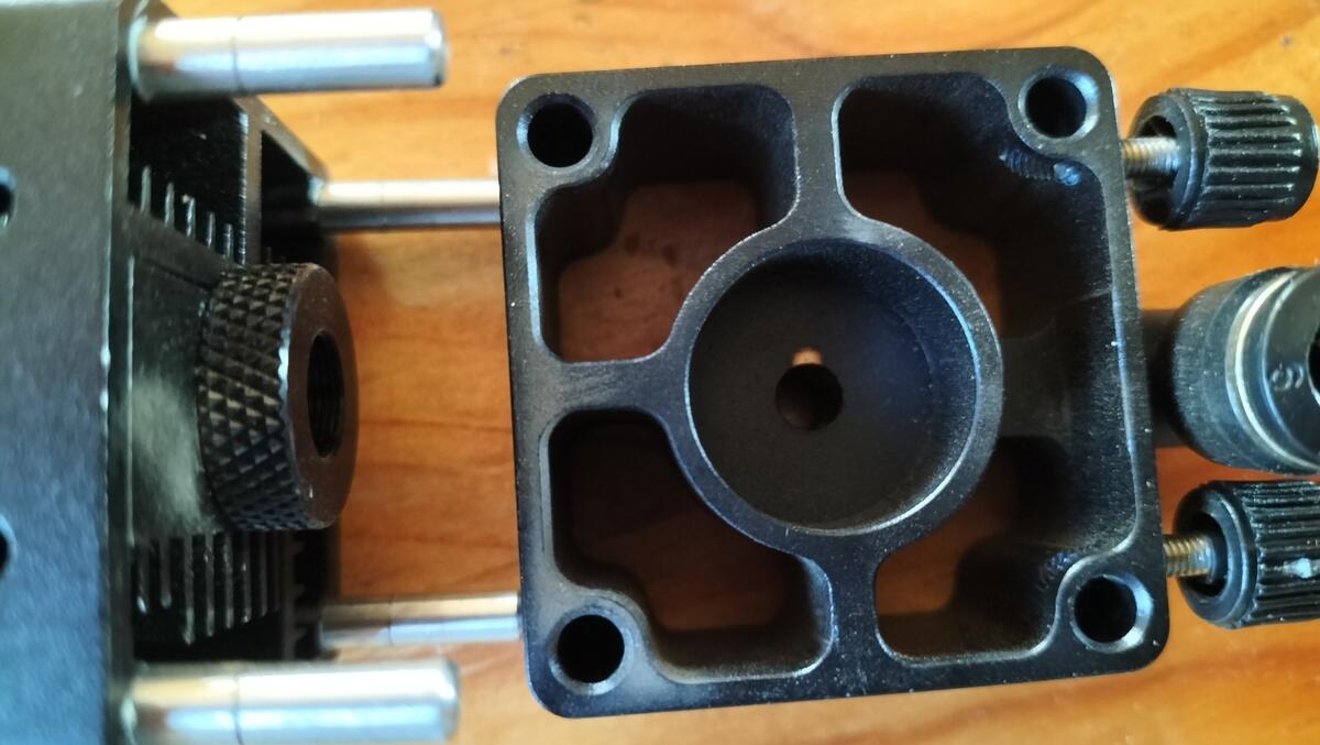
I had previously used a small brush to clean the fan but I could only get to the top and a very small amount of the underside of each fan blade through the side of the module. So this time I removed the top cover and took the fan out to clean it. I also removed the adjustment block from the bottom to clean the fins within. It was then I noticed a small amount of the black paint missing from the side of the centre hole at the top of the adjustment block. clearly the beam had been partially obscured therefore only a very small percentage making it to the material. See the attached photo.
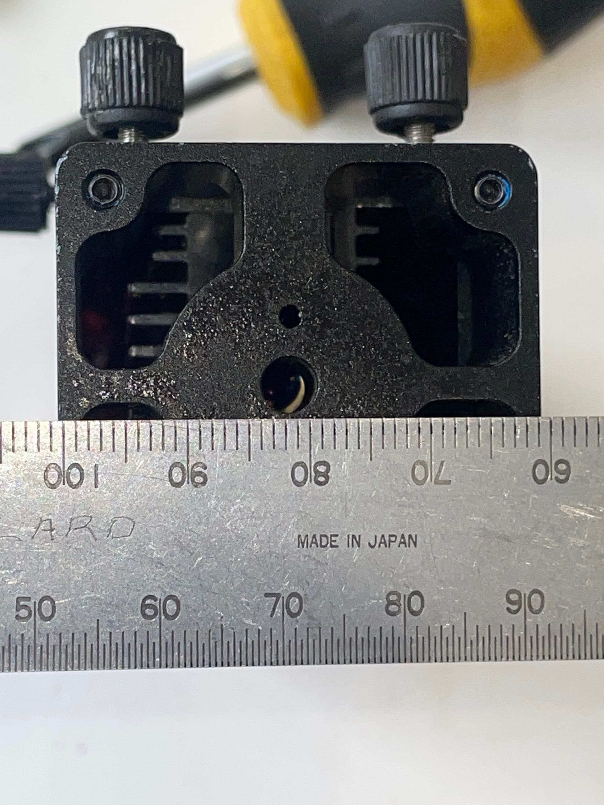
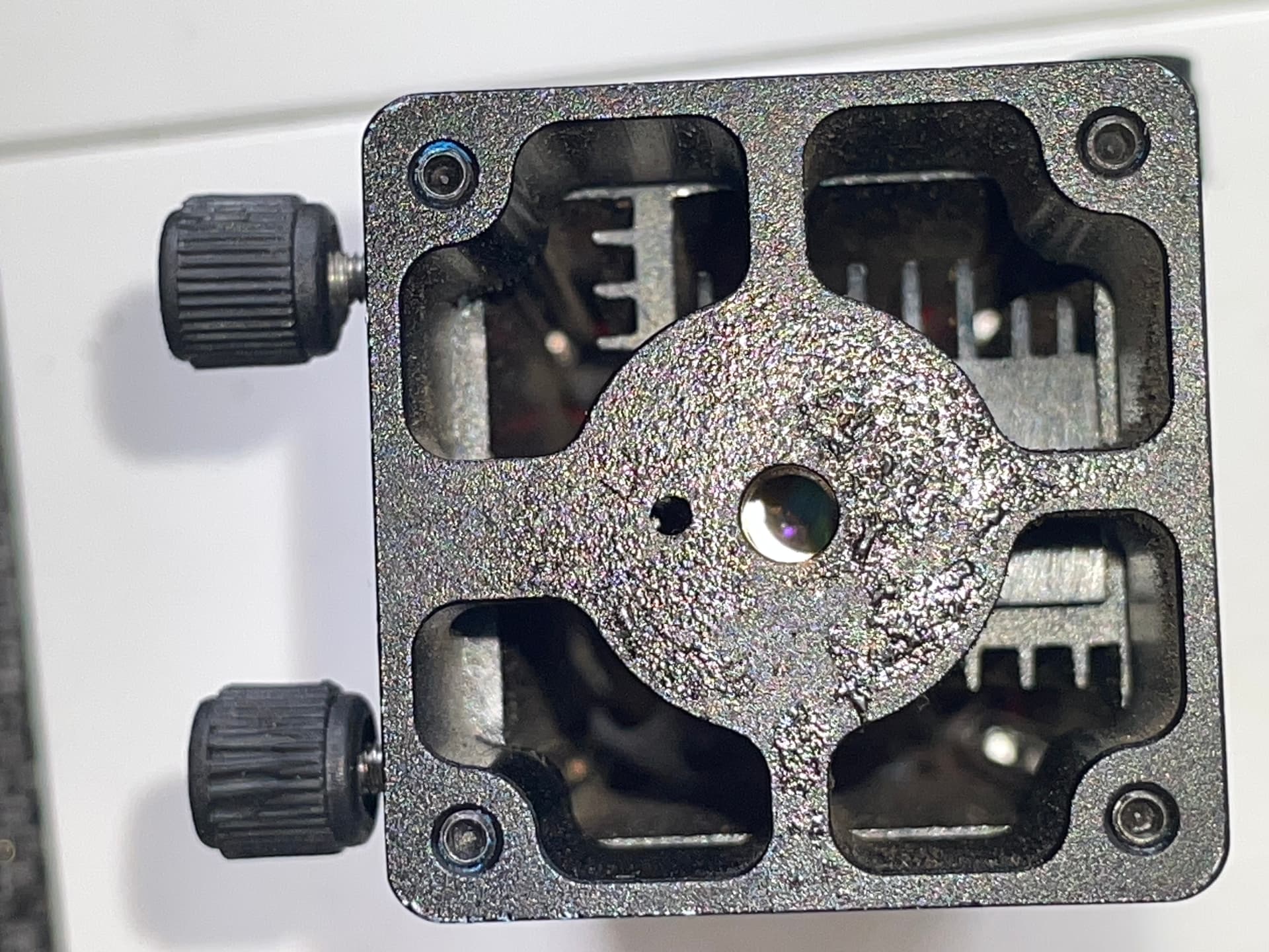
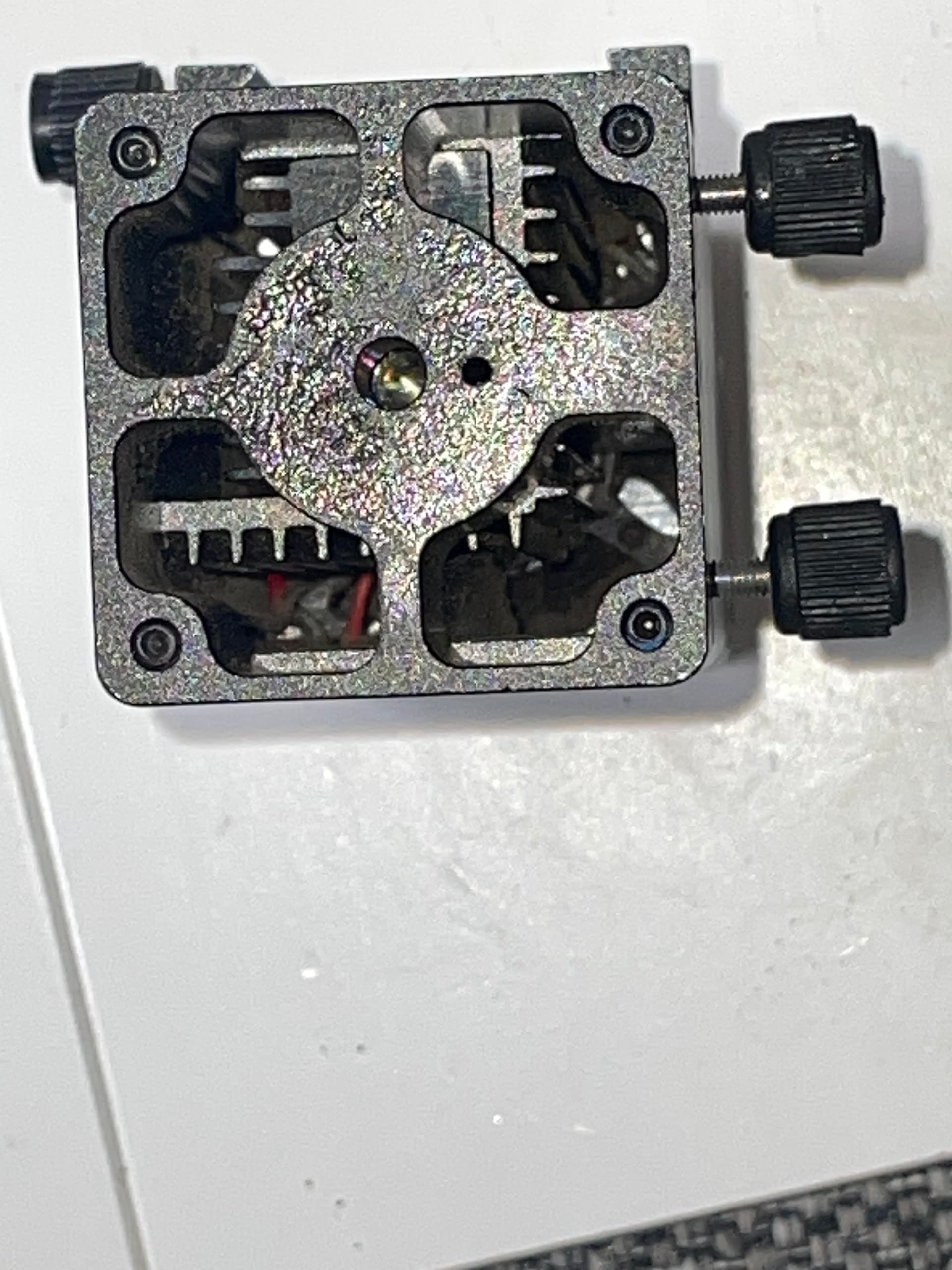
I then found the lens was off-centre by 2mm. There was no easy way to tell which was the correct orientation for the adjustment block. I tried each way until the best fit was found. Photos 2,3, 4 & 5
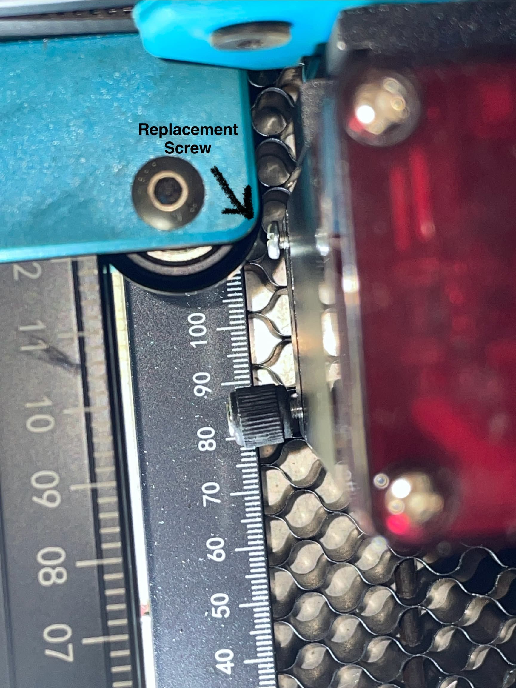
The last photo is the best orientation for the adjustment block so the lens is aligned with centre of the hole but then I found the set screws interfered with the left Y-motor assembly so I had to replace the thumb screw with a short flat head screw to give the full 300 x 300 work area.
Wow! I did not know they came with that part. Glad you found it. I suspect vibration loosened things up, or they were originally loose and just gradually shifted.
Because I see no lens or extra mounting holes, I have no idea why the adjustment plate. It is possible it is replaced with one that supports an Air Assist fitting. Maybe someone that has your machine can tell us.
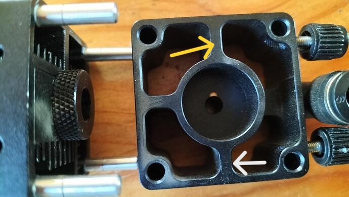
If you look at my photos the block is able to be fitted in four different positions because the four spigots are evenly spaced in a perfect square however the hole for the laser beam is NOT in the centre. My final photo above shows the only way the lens perfectly lines up in the centre of the hole. The fault happened to mine because the thumb screws were fouling the y-motor assembly when x was in the zero position so I wasn’t getting the full x travel. In an attempt to resolve the issue I turned the block by 180° so the thumb screws faced the other way. But because the hole is off-centre the lens was partly obstructed by the block, the black paint was burnt and the full strength of the beam wasn’t getting to the material being cut. To resolve the x travel issue I put much shorter set screws in place and turned the block back to the original position.
Went to bed thinking about this last night! A couple of ideas. A DIY bodge would be to drill out a larger diameter hole that it doesn’t interfere with the laser. A more technical way possibly would be to etch a square with the same dimensions as the laser and with diagonals. The block should be up to the lines marked on the four spigots. Take off the block and centre the laser over the square then fire the laser to mark the surface and see where the laser burns a mark. This will tell you if the laser is at right angles to the surface if it burns where the diagonals cross. What ever it would possibly be an idea to check the lens and try and find out why it has moved or whether it’s just the block. Perhaps a new block would solve the problem. I hope you get it sorted out.
I had thought of drilling it out too but decided not to as it’s size could possibly be correct for air assist air flow. I measured the lens position in the module itself and found it is also offset from centre as well. So the hole in the block can only be centred in one position out of the four ways. This begs the question why the spigots/mounting posts aren’t arranged to only allow the block to be fitted in one orientation. It would only take one of them to be a couple of millimetres off the perfect square that they are now.
Being almost completely ignorant of the whole laser discipline, had I assembled the machine wrongly when I first purchased it I think I would’ve become so disillusioned with it that I’m sure I would’ve given up. Almost everything I know now about the hobby has been self taught or gleaned from this fantastic forum.
I think possibly you may have a duff block that is not machined properly, either that or somehow it was knocked. My block goes seems to go in any position. I would suggest looking at the 20W laser for this machine. It has a very fine beam and would be better for 5mm MDF. I installed one and am very happy with it. I too am a beginner, with little time to “play” with it. My knowledge like yours has come from here and members videos on Youtube.
The fault happened to mine because the thumb screws were fouling the y-motor assembly with the laser head in the zero position on the x-axis so I wasn’t getting the full x travel. In an attempt to resolve the issue I turned the block by 180° so the thumb screws faced the other way. But because the hole is off-centre the lens was partly obstructed by the block. Therefore the black paint was burnt and the full strength of the beam wasn’t reaching the material being worked on. Instead to resolve the x travel issue I turned the block back to the original position and put much shorter set screws in place to clear the obstruction(see the photos attached above).
I had another look at mine. There are two options, the thumb screws to the left or to the front. Either way it fouls the x-axis or the front frame. A design fault that has to be remedied by enlarging the centre hole. I don’t think it will affect the air assist. It’s a mod I’ll try, I don’t use a 10W much I find Two Trees 20W better. Complain to Two Trees and ask them what they are going to do about it. There is too much competition in China now and these smaller companies like to please their clients. I’ve always had problems solved when complaining, in a nice way.