I’ve been troubleshooting this issue for a couple of days now and jumping between whatever posts I can find on the subject. No one seems to specifically have the laser/power supply/controller combo that I have.
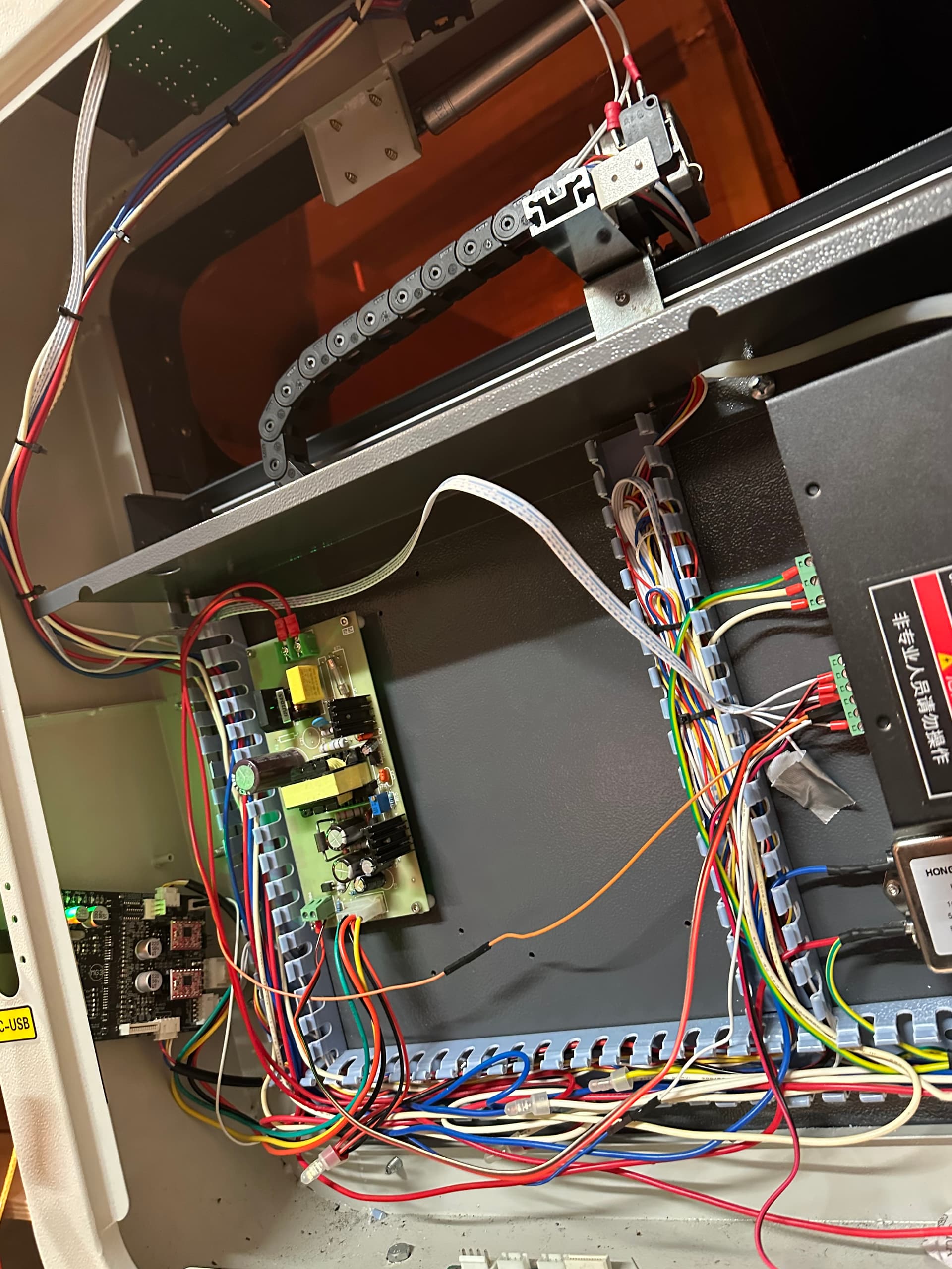
I purchased a second-hand Chinese 4060 50W CO2 and I instantly replaced the controller with a Mini Grbl MG3 so I could use Lightburn. I believe I have followed the wiring correctly however there is an extra component to the power supply that isn’t in the standard K40 installation documentation for the MG3 (given that mine is not a K40).
The long and short of it is, I have a found a wiring config that gives me the laser and motion control but I appear to have no PWM control and the laser remains on during travel moves.
Can anyone help?
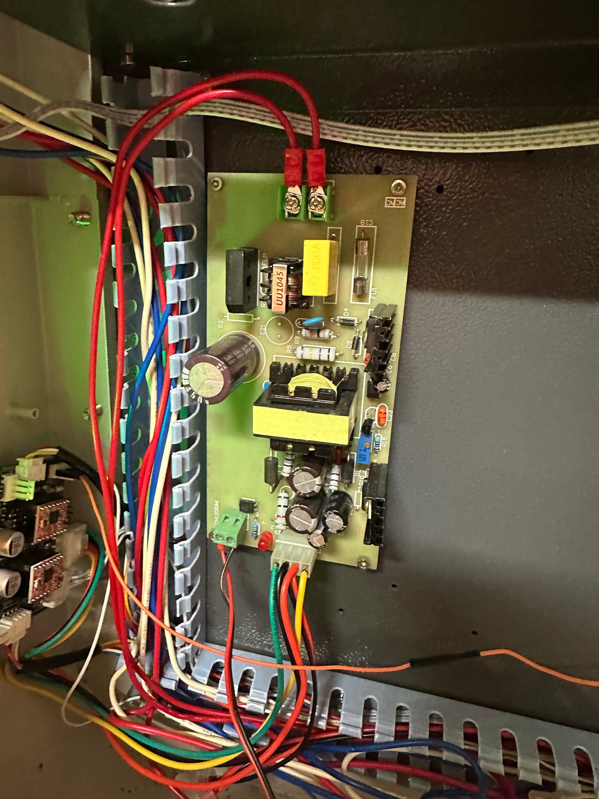
I fear that what I’m looking at is a replacement power supply but hoping that someone can at least tell me that much.
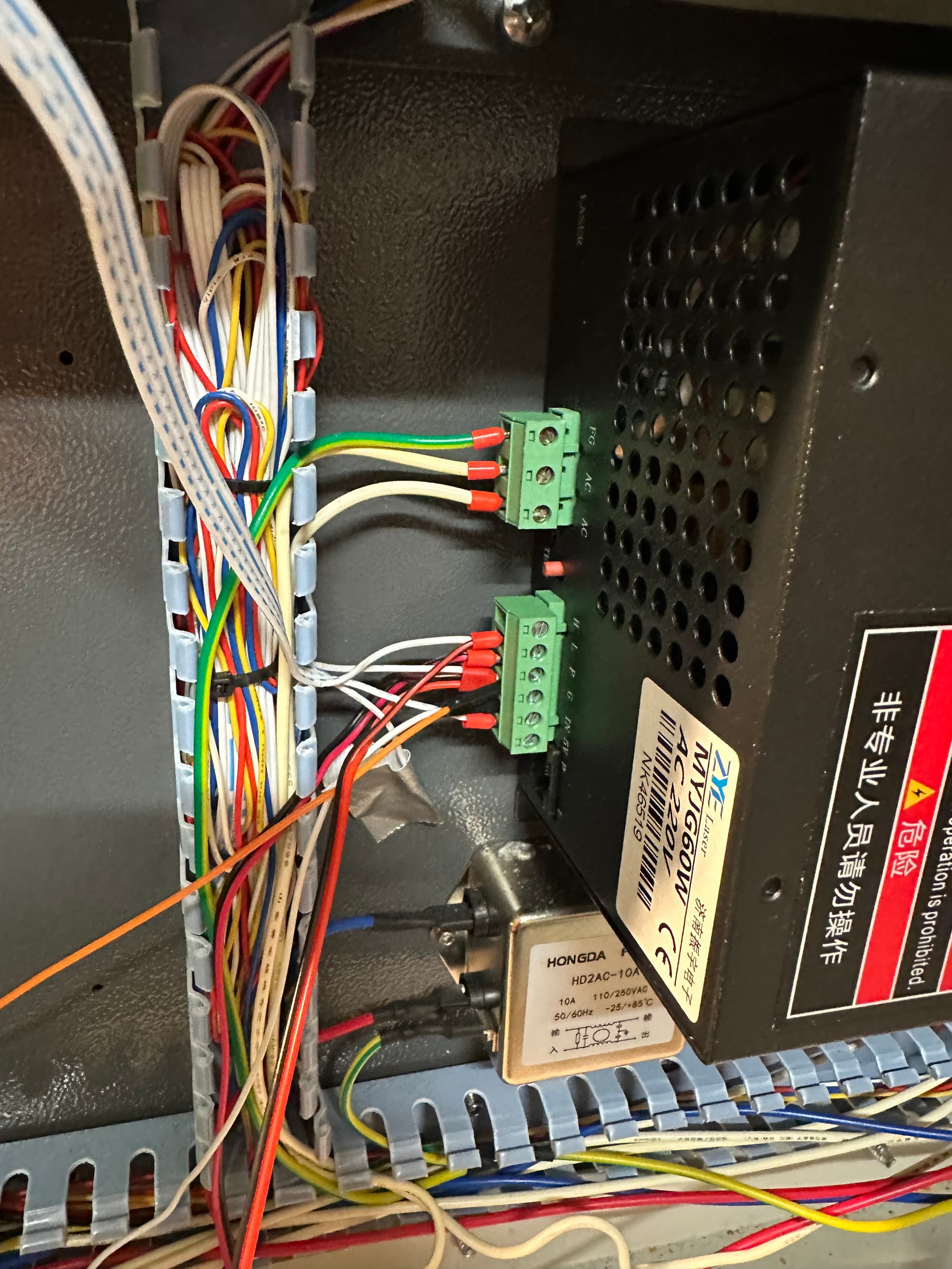
Currently the L is wired to that external PSU board pictured. The “big 4 pin connector” comes from this and goes into the MG3.
The IN is wired to the PWM pin on the MG3
Now I’ve made some progress and solved the laser on while moving issue. The P was wired to a water flow sensor but it seems the board still wasn’t grounding properly until I wired the Ground from the LPS to the common ground J2 pin on the MG3.
Now I just have no PWM for the laser.
Wondering if I need to connect LPS ground to the ground pin by the PWM pin on the MG3
In any electrical circuit like these there needs to be a common signal ground to all components.
I am clueless what the board wired to L is ? Can you explain?
These really work simply…
The lps has two signal lines… IN and L on the lps.
The L may also have an H that is another inverted input of L.
Tube current is set by the voltage/pwm on IN.
The L is a laser enable line and is active when it goes low.
When L goes active, the tube should lase at the current determined by the IN voltage or pwm.
It’s kind of important to know exactly what is driving the L signal.
Most of the K40 have a pot on the console or digital display. This is usually wired to IN and the pwm is feed through H.
Looking at the suggested wiring, I think you (we) need to know what that board driving the L input, does exactly…
If you have a voltmeter you can measure the IN (or pwm output) and read it’s voltage. It will be the pwm percentage times 5 (ttl signal) 50% pwm should read 2.5V