Non-uniform grid spacing from galvo

I am trying to do precision engraving for a printed circuit board

The lens calibration works fine. But I find when I make a grid of 1-cm spaced dots, the distance between the dots at the center is smaller than at the edge. By measuring this, it is clear this is coming from the angle of the galv to the distance on the bed NOT being a linear function, but obeying theta = arctan(d/f), where theta is the galv angle, d is the distance from the center on the bed, and f is the focal length of the lens.
Would it be possible as part of the lens calibration to add one additional parameter, the focal length f, and to do the above arctan correction to make the grid evenly spaced?

Thanks

When you configure the machine by using a config file or a corr (correction file) the machine knows you’re focal length. My factory markcfg7 file not only had configuration details but also lens correction for my F420mm lens.

If it didn’t, it couldn’t determine how fast the surface scan would be.

Maybe you could clarify what do you see? A photo would be nice.

What lens and what size are you trying to attempt?

What you’re speaking of sounds like a faulty lens correction.

:grinning_cat:

Thanks for the reply and discussion. I think this can make your product even better.

I am using a ComMarker Omni X system, with the 150mm lens. In the USB stick distributed with the machine, there was no configuration file. As recommended by ComMarker, I had to do the lens calibration myself, using the Lightburn program “calibrate galvo lens”. This worked fine, and I was able to correct for scale, bulge, skew and trapezoid.

In this note, I would like an additional correction parameter for angle non-linearity, having to do with the galvo angle and the distance on the build plate being slightly non-linear, scaling not as theta but tan(theta). This is a non-linear correction to x from x (going as x^3), not as a correction to x from y, as in bulge, skew and trapezoid.

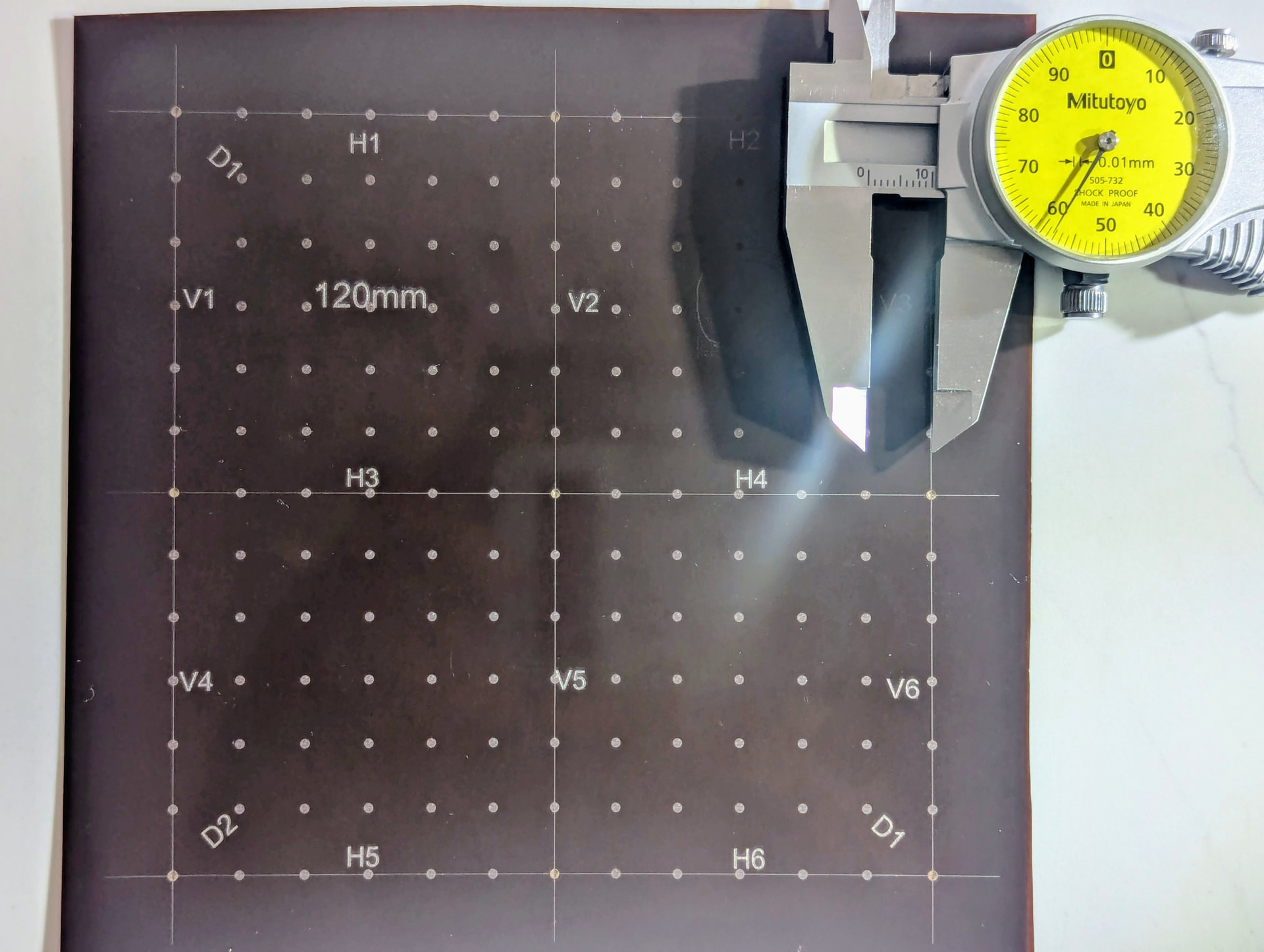
Here is a photo of the test calibrator I made, which is similar to the one in Lightburn but with more distances (1cm spacings) and labeled to make things easier to measure. Note, I designed the round holes to be cone shaped into the plastic so that it is easy to insert the caliper points and measure the distances more accurately with a caliper. (I’ve check for no bias here.) When I measure the spacing at the center, I find 9.9 ± 0.05 mm, whereas at the edge I find 10.6 ± 0.05 mm. You can even see by eye that the spacing is greater on the outside.

Because I am trying to use Lightburn for laser machining of a flex circuit board, I would like to calibrate with this additional correction, which seems to be a simple correction from distance proportional to theta to tan(theta), for both the x and y axis. I have also figured out a way to use my calibrator to iterate on the Lightburn “calibrate galvo lens” feature to do the lens correction even better, using this precision measurement with calipers.

In the Lightburn program, I looked at the “prefs” file where all the calibration information is stored, and the only reference was to the “height = 150”. I have checked by changing this value that it tells the program the size of the bed. It seems the program does not know the lens height. But maybe all that is needed is a rescaling of the internal galvo theta from theta to tan(theta), or maybe with a scaling factor that changes the dominate theta^3 term in its Taylor expansion. I am assuming the calibration program gives the 150mm size of the bed, after which it can compute something like the scan speed.

I hope you can help here. I think with this correction and caliper calibration one can get quite accurate positioning of a pattern, opening up new applications for systems that are not too costly. I can share info about details (files, purchase list etc) if that is interesting to you.

Thanks
John

You’ll likely have to wait until the weekend is over and hang in there until one of @Lightburn people can check it out. With fiber machines, I don’t know a lot compared to what I do know.

There’s a couple more technical people around, such as @Albroswift. Maybe he can chime in.

:grinning_cat:

Interesting.

How far off is an inner pair of dots compared to an outer pair of dots?

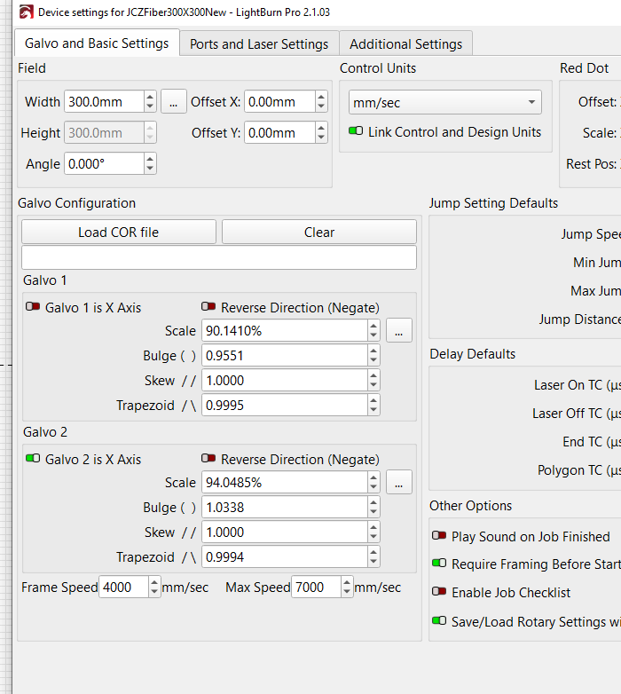
You mentioned trapezoid was calibrated, what are your values? Just curious.

The talk around the campfire is we will have 27 point correction eventually, that will help with lens distortion.

When you do the final scale adjustment, where in the field do you take your measurements? My inner to outer variations are almost zero over 3 different lenses but I do the final scale adjustment about halfway out.

Are your circuit boards close to the whole 150x150?

Your technical understanding of the process is way above my understanding so I can’t comment on any of that, only the tweaks to get the last little bit out of what we have to work with presently.
Following along!

As I mentioned in my previous post, a spacing of 9.9mm at the inner sesction inner, and 10.6mm at the outer.

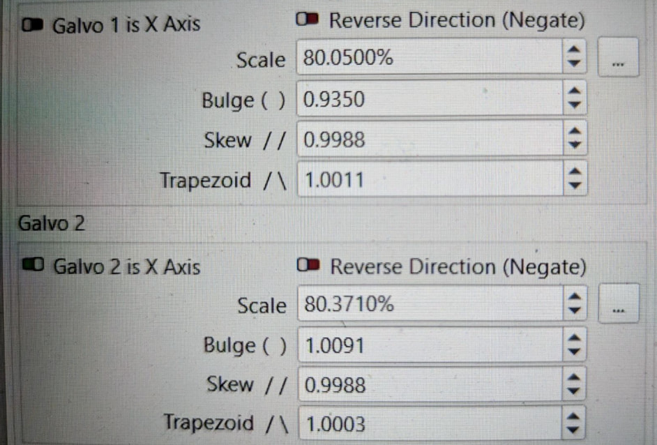
Trapezoid is X: 1.0011, Y:1.0003, very small. The trapezoid should not correct for this error, which seems to be only a function of x for the x correction, not a function of y for the x correction

Yes, my measurement is basically looking at more points as you say, but what I find is that the next correction is not big, but seems to be this kind of error. Note that taking more points is really a pain if you have to measure it by hand, and not accurate. This is why I am burning cones into the material, so that it is fast to measure with a caliper. Also note that I am planning to use a digital caliper with a bluetooth connection, so the numbers can be entered into a spreadsheet automatically. If the Lightburn software was changed slightly, it could then also be entered into lightburn with a push of a button - you want the calibration windows to go to the next entry when you enter a number and hit return; I will ask Lightburn next for this small change.

Right now, I am only comparing measurements at the inner and outer separations. However, as I look at the image, my guess is that only this angle distortion matters at this point. This might only need one number for both x and y, and maybe can be calculated if you know the focal length of the lens. For your measurements, what hardware are you using, since maybe your machine has this correction already built in?

For now, I am etching a small kapton piece as part of a microwave connector, which is only about 3 cm across. I have been able to align my pattern to my piece reliably to about 50um. So this distortion will not hurt me for my current project, but I am seeing if I can do better for more complex projects in the future. This is for quantum computer hardware.

Yes, I think if I can tweak this, this inexpensive system can do small jobs that would normally require a quite expensive dedicated machine.

Missed the 9.9/ 10.6 , that’s a pretty big difference over 150mm. Understand the trap wouldn’t affect it, I’m just curious. May be an indication of lens accuracy or maybe just electronics. What is the skew? Next time I’m in the shop I’ll try your test grid see what I actually have.

Yes, I was surprised it was this big, but I think expected from the angle geometry. Thanks, it would be nice to have another measurement. Here are my parameters; taking a picture is the best way to make sure no transcription error.

Another idea—though just a workaround—would be to use your distortion matrix to adjust the project file itself. That’s not the “clean” way of doing it, but it would also result in the same outcome. Nowadays it’s easy to vibe code a tool that takes your measured matrix and distorts the project contents as needed so that it comes out correctly.
I did this recently with the rotary distortion (Rotationslaser Vorverzerrung – Laser Tools) where you define the shape of the round object (your matrix), and the tool computes a distorted image that is then imported to LB and not changed there anymore.

Did you manually measure/ adjust your skew or did the 9 point correction generate it? Sorry off topic but just curious. Mine always came out zeros, I just assumed 9 point didn’t calibrate skew. Maybe I’m missing something in the procedure.

I calibrated with 9 point. Since the skew corrects for the x and y axis not being orthogonal, it probably has to do with the setup of each galvo. Mine is slightly off, but yours was built perfectly.

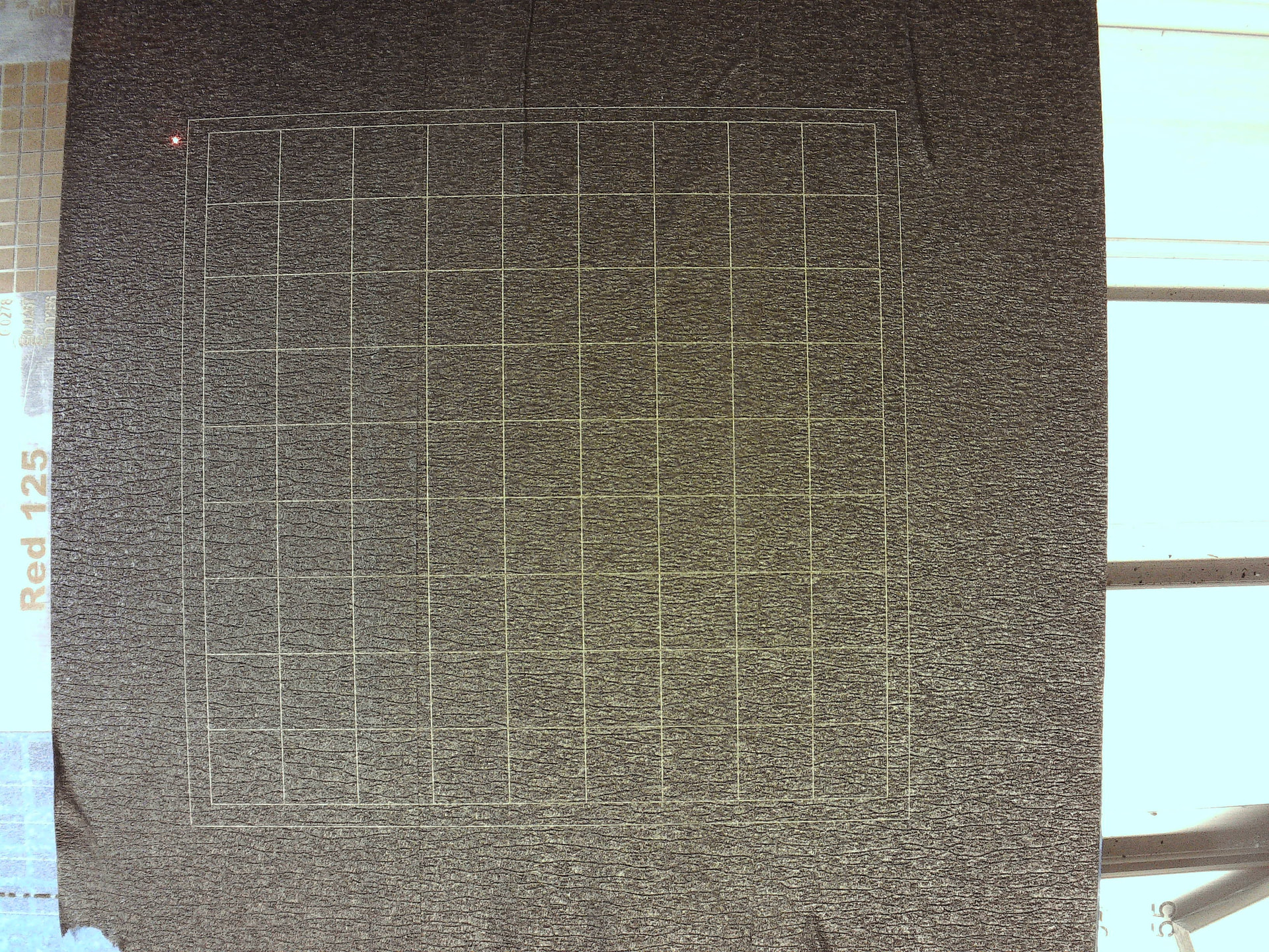
I have the 100X100 in right now so did a 90x90 10mm grid, measured a little over 127mm corner to corner, squares were equal in size and 9 squares = 90mm at edges and center 1 square was 10mm x 10mm where ever i checked, obviously measuring lines on black tape isn’t a super accurate method, but same method I used for 9 point. Next time I have a larger lens on I’ll give it a try.

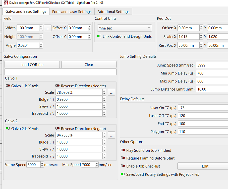
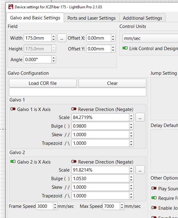
60W MOPA SG7110 Galvo no brand name on the lenses 2022 XT Laser build Speed 300mm/s 20% power 20kHz 2 passes

100X100 no trap no skew

the 300X300 has a little trap

175X175 no trap no skew

Thanks for hopping in..

:grinning_cat:

Not much help I’m afraid but I like discussing. Maybe learn something.