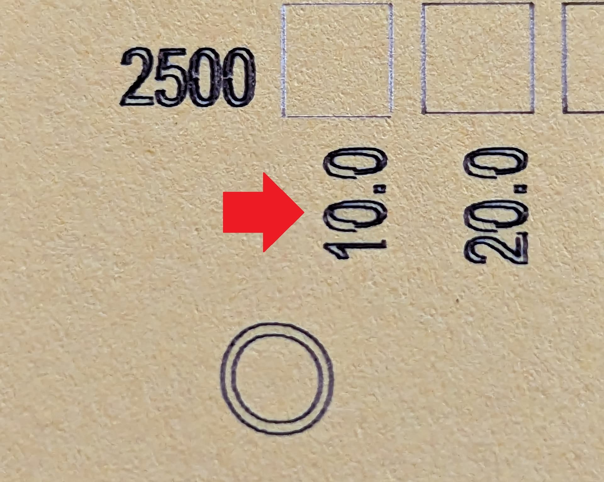
Hey guys, I have an issue with the start and finish points on all movements in my laser projects, but it is only on the Y axis. I have torn down and rebuilt my machine more than once now, tried two different controllers, different stepper motors, and readjusted the motor axle grub screws, belts and v-wheels more times than I can count, and this issue persists no matter what. It happens in the same amount, regardless of speed. I’ve ran the machine from 5000mm/min all the way down to 200mm/min and still have this issue. It’s not just bidirectional scanning, either. If you look at the zeroes along the bottom line in the photo from my material test run, you can see that the inside and outside walls of the zeroes are not parallel, leaving a thin point where it starts and a thick point where it finishes. In the filled square picture, you can see that the lines start and end at different points when switching directions, but only in the Y direction. I tinkered with scanning offset settings a bit and I can get the issue to disappear on the Y, but the settings then throw the X off instead. The pictures attached are with no scanning offset, and 5% overscan. I’m not really sure what else to look into at this point. What do you guys think?
I have an openbuilds ACRO style machine, Arduino + CNC Shield v3, A4988 drivers, 24v 14.6a meanwell power supply, and a generic 10w optical output diode laser. I’m running Lightburn on a Win10 pc.
This is classic mechanical backlash, due to a loose something from motor to laser beam.
Unfortunately, finding the root cause requires a methodical and meticulous hunt along the entire Y axis path, without assuming you’ve already looked at everything.
This guide may be of use, although it’s for Sculpfun machines:
Searching the forum posts for “backlash” will reveal many prior discussions. It’s worthwhile to note how many folks started out certain it’s a software problem, only to eventually discover a cryptic screw / belt / bracket has been loose all along.
Yeah, I’m definitely going to keep hunting. But whats bizarre is that the offset is exactly the same even at incredibly low speeds, there’s almost no variation from slow to fast like I would expect from backlash typically. I’ve also swapped out the entire Y axis system more than once now, trying a single motor to axle approach, a dual motor approach, etc. And I haven’t seen any change at all in the results no matter what I adjust or retighten. It’s bizarre. It had me wondering if my generic laser’s control board was triggering slower/faster than it should, but it doesn’t happen on the X axis, so I ruled that out… I’m at a loss. But I will keep hunting, and maybe try a different transmission system altogether, and ditch the belts.
Edit: I’ve also tried different motors and pulleys on the design.
Looking at the OpenBuilds ACRO layout, that gantry rides on chonky hardware with plenty of opportunity for slop, no matter how slowly it moves. Perhaps this is a matter of the entire gantry tilting forward-and-back due to the torque around the rollers from those way low motors acting on the pulleys.
Rather than lost linear motion, consider where the gantry can rotate on slightly loose or overly squishy rollers, pulled one way or the other by the belts on the motor pulleys. That would produce a more-or-less constant torque, regardless of speed, and thus account for the displacement along the Y axis.
It won’t be much, but a little wiggle is all it takes!
That’s a really good point. I’ll dig into it deeper, and try to come up with a good way to affix things more solidly for another test run. I’ll report back asap, too. Thank you!