I think, unless I had a thermal camera, my next step would be to plug it in individually and outside the enclosure, to a separate circuit, and see if it works.
Thanks.
Here in Portugal the water pipes are almost all plastic. Earth is connected to a ground copper rod.
Depending on the AC protection scheme (IT, TN or TT)
Earth (green and yellow)(ground) = Ref 0V
Neutral (Blue) to Earth ≈ 0V
Live (Black or Brown or Gray) to Earth and to Neutral ≈ 230V - 240V.
Here in the UK you’re not allowed to bond Earth and Neutral on the customer side except in special circumstances, (Only the electrical network are) as it’s [in theory] mostly TNS-PME (we get a separate earth and neutral to the consumer unit) and bonding them would make a PEN. Everything should be earthed like boiler pipes etc. Our colours are the same as yours, though our voltage can reach 250V.
Here till now I only found TT.
So simple.
In the U.S., the pole transformer is center tapped. In those other contries, it is not, so 240v is the only option.
In the U.S., if you have balanced loads on both 120v legs, you have zero current in the neutral.
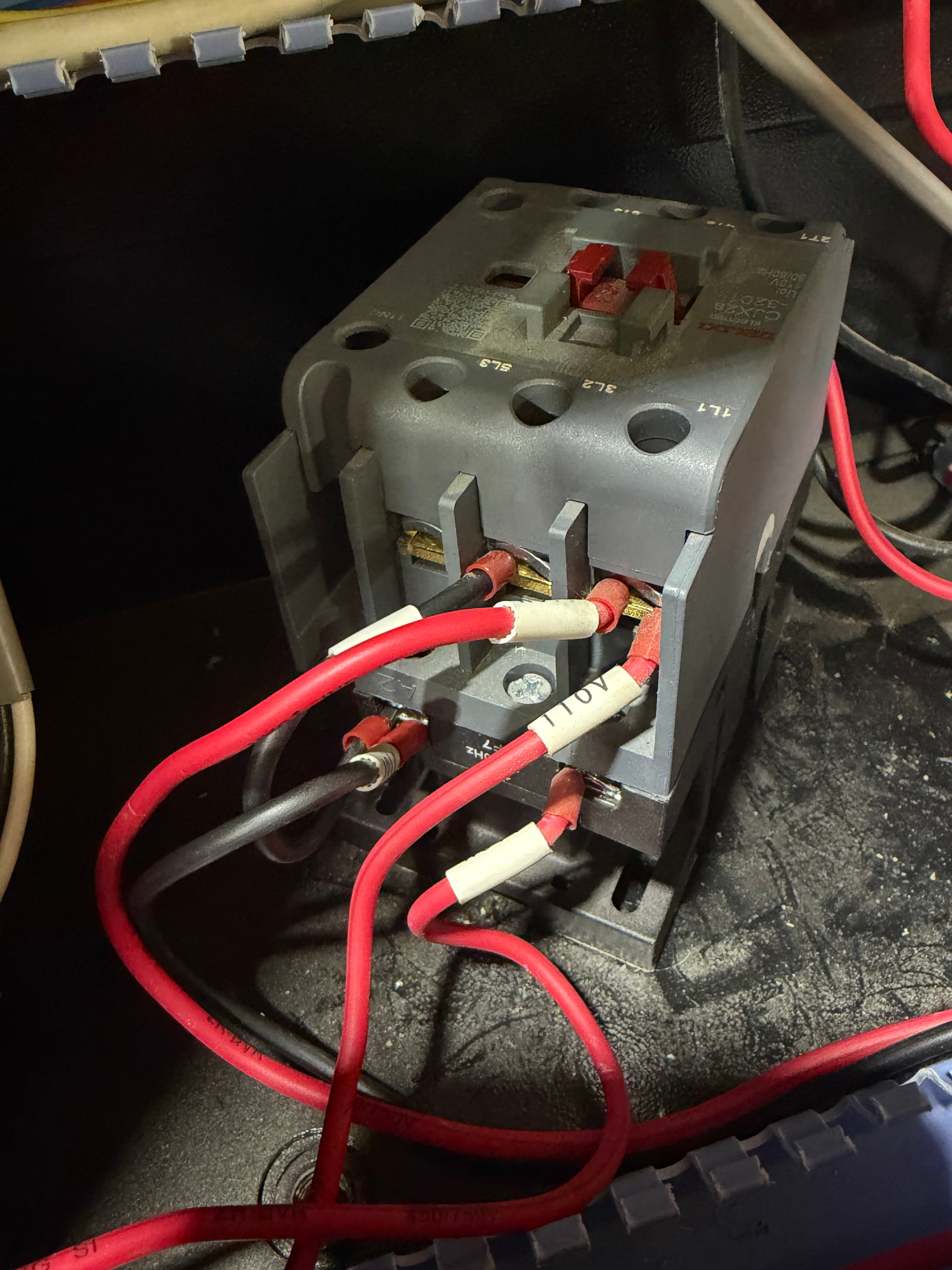
The relay terminals are another good place to check the voltage on the power supply wires. ![]()
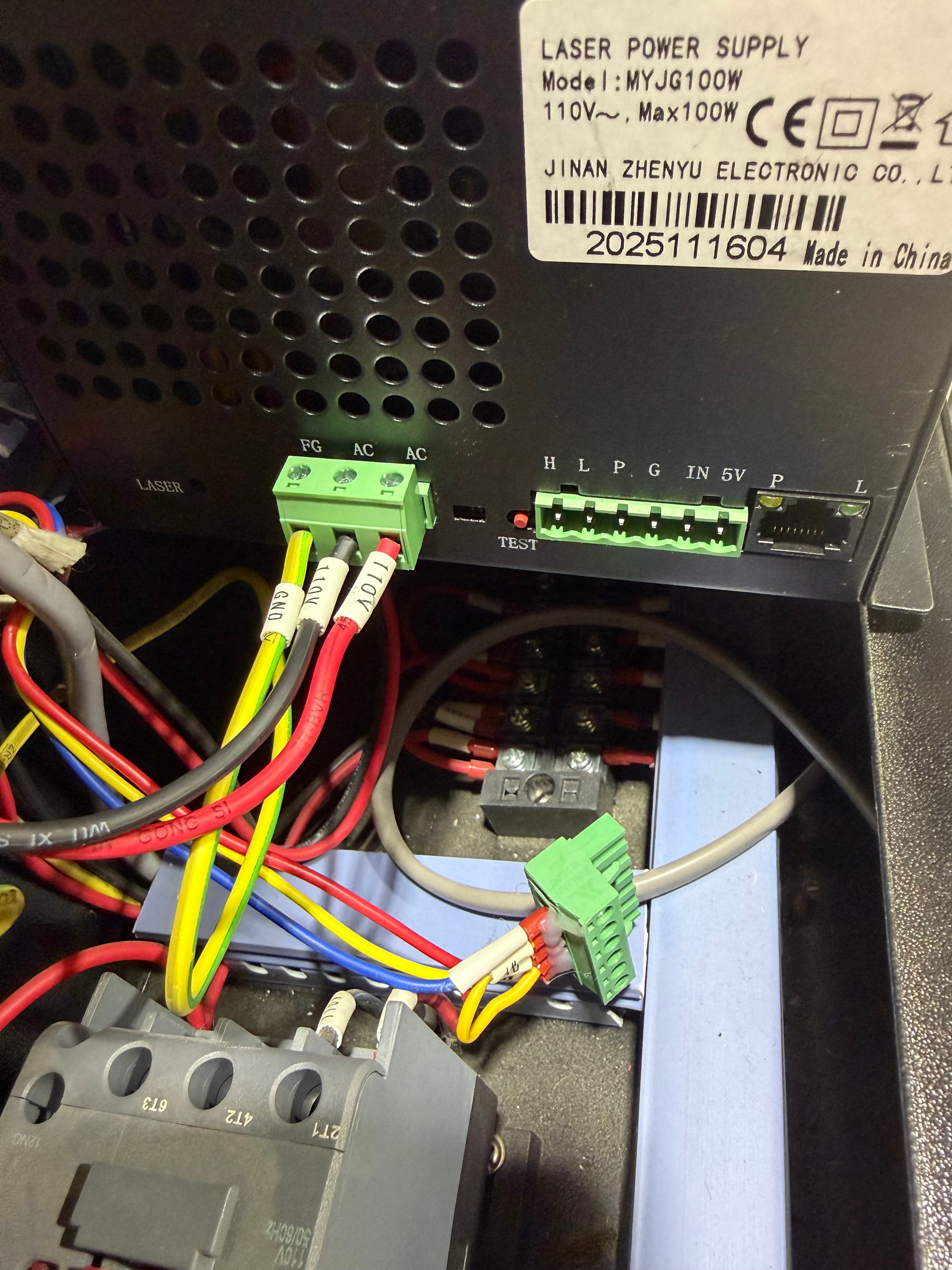
The power supply data plate shows it’s a 110 VAC unit, so one wire should be 120 VAC and the other about 0 VAC with respect to frame ground.
In reference to GND both of those wires have 120V.
That’s why the power supply doesn’t light up: the wire that should be Neutral is either hot or disconnected.
Because the voltmeter presents a very small load = very high resistance, a disconnected wire can float “high”. If both wires are connected properly, the voltage reading will be correct.
The wire colors are meaningless, so you must trace them back to their source. At some point you will measure 0 V on one side of a switch / relay / terminal block and a different voltage on the other side, both measured to frame ground. Whatever is between those two points is the problem.
So I am now leaning towards the contactor. I did some continuity checking and I am getting continuity between A1 and A2 on the relay for the contactor. So my buss bar are all connected now also.
There’s also sometimes a fuse hidden in the power cable port on the exterior of the laser itself.
A1 and A2 on the contactor should always have continuity, usually around 300-400ohms for 250VAC, so probably around that half that for NA.
If you have 0 ohms (or similar) it’s a short. If you have OL, the contacts are broken.
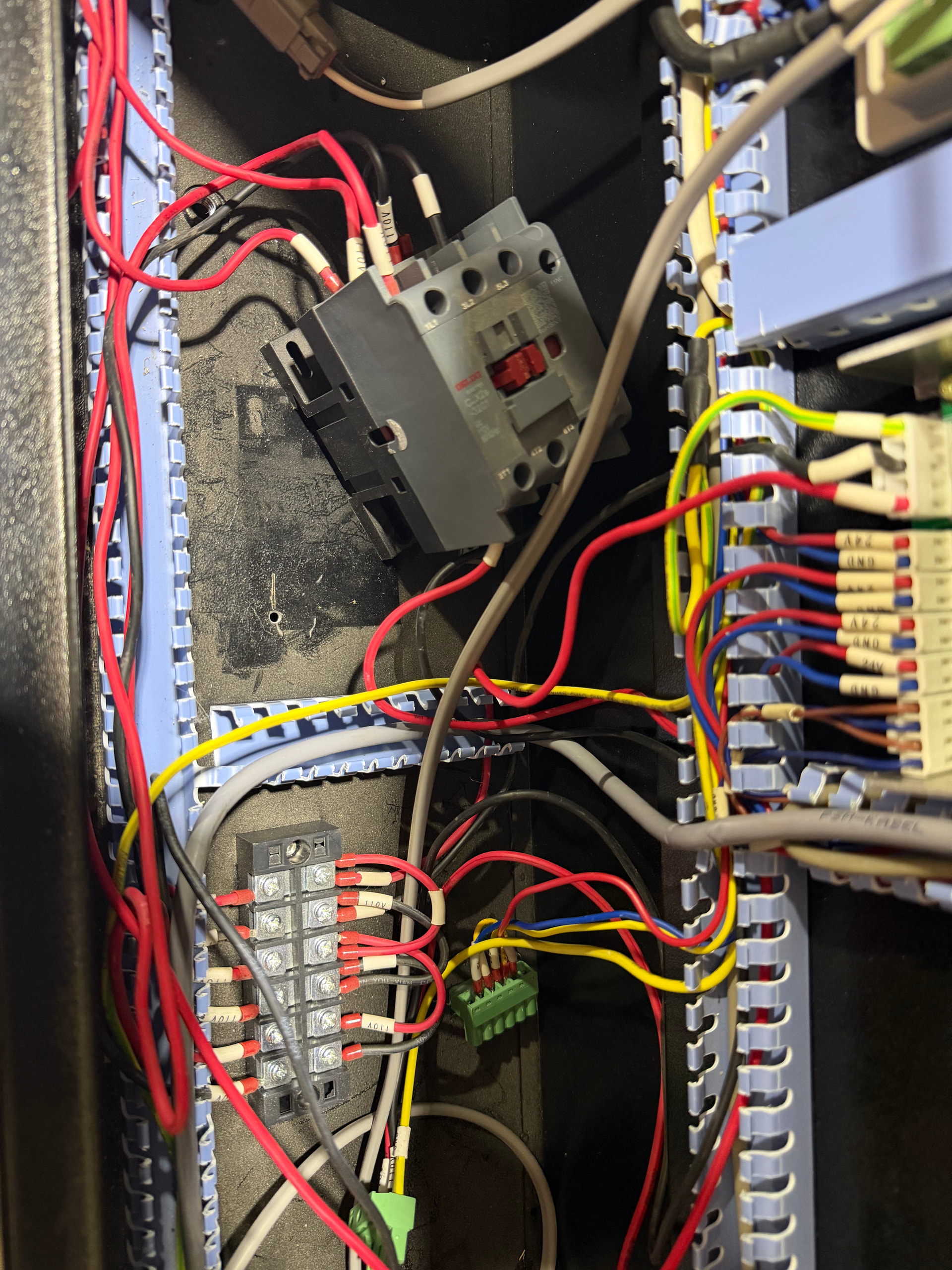
It sounds and looks fine. (other than I’d combine some of those ferrules but thats not relevant to this) Contactors are very simple, they are just switches.
If you want to check if it’s working fine, remove all the wiring. Put voltage across A1 and A2. Listen for the click. Remove the voltage. Listen for the click.
1L1 and 1L3 shouldn’t have continuity. Nor should 2T1 and 2T3. 1L1/1T1 and 1T1/1T3 will have continuity only when 110V is applied between the coil (A1 and A2)
So I would like to start out by saying thank you to everyone that has helped me on this issue. Everyone here is awesome and willing to go above and beyond walking someone like me through troubleshooting.
I found the issue. After doing all of the checks you guys have been telling me everything was checking out. There was no issues inside the laser (I now have to put everything back so that should be fun). I have my laser and water chiller on a cart and they are plugged into a power strip (I have them on a smart plug so I can tell Alexa to turn on the laser and everything turns on). Out of stupidity and desperation I decided to unplug the laser and plug it into the wall directly… and it turned on (the LPS). The wired thing is the water chiller worked fine and so did the rest of the laser. So the power strip took a crap.
So again thank you guys for all of your help and patience walking me through this.
PS now I’m going to have to try to return the second LPS I received when I thought that was the problem.
Good job, congrats! By the by, this is why I suggested the below. It’s always best to try and isolate the problem from the overall circuit.
Oops. I am guessing I read that and was so tunnel visioned on the LPS issue that it didn’t click what I read. So sorry about ignoring the advice that would have saved me some time.
Well if the power strip crapped out then it likely was either faulty, or acted as a fuse in the system, saving your more expensive hardware from failure. Great news!