I was poking around on the web yesterday looking for some help on an issue I’m having on the laser. It stopped firing last night in the middle of a job. The head was going through the motions as though nothing was wrong, but no laser firing. I checked the tube and didn’t see any evidence of damage (no cracks that I found or anything). I also checked the water pump it it is working. On a whim, I turned off the water check in the firmware and this made no difference (I did turn it back on for safety).
Best I can tell, it seems like the power supply, but not sure how to confirm this? I don’t have a milliamp meter yet (arriving this week) which I’m going to install on the return line from the laser (that’s where it goes, right?)
Am I on the right track? Any tips on replacing the laser power supply?
Also, the one that came with the cutter is hardwired, I found the laser quick disconnect on Amazon and am going to install that- seems pretty straightforward.
Probably, but you can check the inputs to the supply, usually L and IN. L goes low to enable the supply and IN is the PWM input to control the tube.
If these are correct, it’s probably the supply. I’m sure a failing tube is in here also, but I’m not sure how one reacts when it’s failing. If the current goes up or down.
That machine is pretty new for these types of problems. Have you spoken to the seller?
The machine is about 4 years old (I think they went by Orion Motor Tech before shortening their name). Actually bought it through walmart.com, so they won’t be much help
When checking the inputs to the PSU, is this something you’re checking with a multimeter or is there something you can physically see (like an LED or something)? I haven’t done much with these HV power supplies so wanting to take my time with it.
Understanding how it works is crucial to safety with anything. Anything you can get to that isn’t insulated is safe to deal with. Meaning measuring voltages and so forth. The controller output (actually ‘sink’ current) pull the voltage to ground and it’s maxed out at about 32volts upper limit (controller.) So a voltmeter is safe for any of these checks. Mine are the standard 24 volts.
There is an anode wire to the tube and it is the High Voltage, most are wired directly to the anode of the tube. This is the dangerous end for voltage the opposite end is dangerous from laser output viewpoint. Anywhere there is HV take extra care. Most of it is safe if the insulation isn’t broken.
Resist temptation to open the HV case, generally there is little to test and few schematics to go by. Measuring the output of the HV supply requires the proper test equipment or a good medical insurance policy.
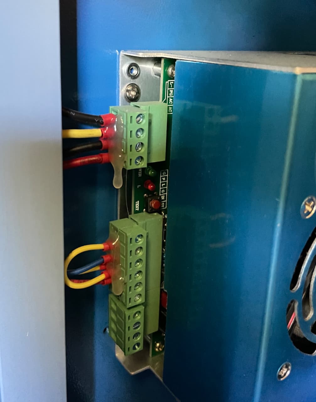
This is my power supply. The L input ‘enables’ the lasers control. Mine also has an H input. L input is active low and H is active high. The PWM output from the controller goes to IN on the power supply. With L enabled (active,) PWM will now fire the laser when it goes high.
You should be able to measure either of these two inputs with a regular voltmeter. The PWM will vary from 0 to about 5v depending on the power setting.
If these two inputs are active and no lasing is happening, I think you’re at tube or power supply…
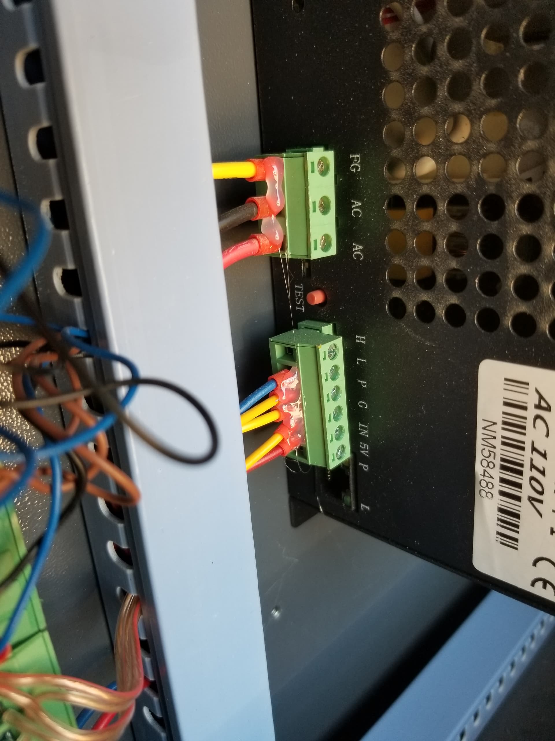
Thank you for breaking this down a bit more for me. I uploaded a pic of my connections and they are a little different, but pretty much the same.
Looking at mine, the first connector has (top to bottom):
Laser Return (is this the line I jump the milliamp meter into?)
Ground
AC Neutral
AC Positive
Second Connector
Ground for water and Laser
Water Switch and Laser
Laser Power (check this w/ multimeter? Should this be 24V when the laser is switched on?
Ground (ground appears to be coming into this port and jumped over to position 1)
IN Input level (check with w/ multimeter? (0V-5V) depending on power?
Will def stay away from cracking the HV case open.
One more question- as my laser HV line is hardwired- I bought a quick disconnect so I don’t have to completely do the connection to the tube if my PSU goes out again (assuming it’s this). Is there any capacitance in that line if the system has been powered down for a few days? I’m going to need to cut that line and install the connector. (I’d have to disconnect it from the tube anyway).
Sorry for all the questions. Hopefully, this will be it
I always ground my tools until I’m sure it’s discharged. If you can ground your ‘clippers’ it will sink whatever is left through them when you clip it.
I usually have a ground wire to ensure it’s discharged.
There are many variables when it comes to HV stuff. Keep safe, ground the connections before tampering and you’ll be fine. Don’t forget that tube could be a capacitor, so assume it’s ‘hot’ also. Haven’t heard of it, but I saw it enough in fixing tube gear.
Looks like you’re hooked up alright…
It should ‘fire’ with the ‘test’ button. I’d give that a try also…
On mine, there is a black wire coming from the cathode end (where the beam comes out) that goes to ground, probably laser return, but it could be grounded anywhere.
Correct.
The Laser Power I’m not sure what the voltage there will be. The supply runs off the mains, so I’m not sure about this one. Shouldn’t hurt to measure it.
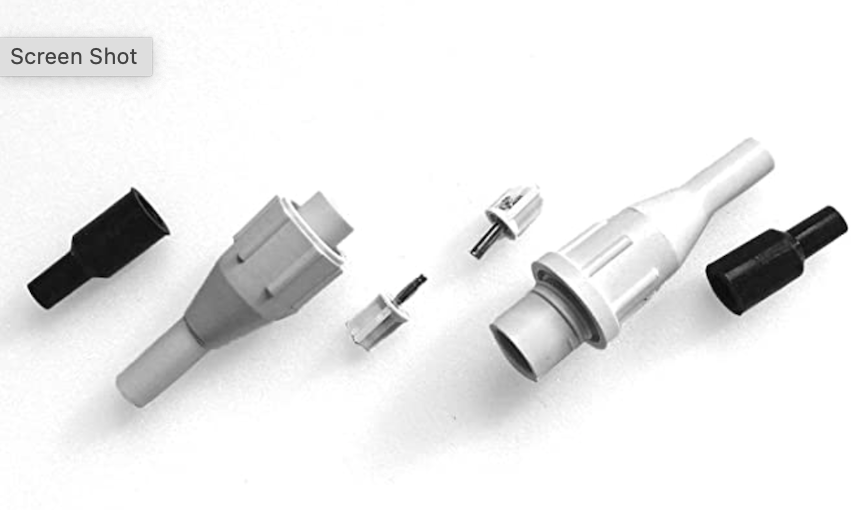
Today is the day (hopefully)- the new PSU should deliver with a little luck. In my quest to update things and make life a bit easier going forward, I’m also planning to add in the HV disconnect as shown below.
One thing I can’t find is any real instructions to install it other than a sped up video of about 30 seconds. Has anyone in the group installed one of these? Seems like it will make things easier, especially if my replacement bulb down the road is pre-wired.
My assumption is the female end of the metal lead insets into the solid threaded connector and spot hit with some hot melt glue at the screw post and the connector to the wire (or the supplied silicon from OMTech) an the male end with the coupling that freely spins is the end coming from the laser.
Does anyone have any experience installing these? Do I have it right or is it completely backwards?
Thanks Jack- I have a grounding rod outside my exhaust window I installed when I got the machine, just in case the internal grounds were questionable. My plan is to take some wire, attach it to the frame ground (or directly to the grounding rod? and wrap it around the metal end of my cutters and snip it. I’ll let the thread know how it went. Fingers crossed everything shows up today.
The ground you need it back to the HV supply, that’s where the HV is ‘heading home’ so to speak. My HV supply is grounded to the frame, maybe yours is also.
Found this advertisement that shows how they go together. There’s some other graphics there. What the red part and screw connector is for I’m not clear on.
I’ve just ordered a pair of them for my HV meter on my China Blue machine.
The red part is heat shrink and I think they intend the screw connector to go on to the post of the tube. If yours is set up like mine, I don’t think you’ll need them, especially if you’re splicing into the existing line to the PSU.
It was the power supply. Replaced it with a Vevor 50w and running well again. I also added in the milliamp meter, HV disconnect and shutoffs to the water supply into my igloo cooler (no chiller yet). I also noted that the laser tube from OMTech originally was turned in such a way that I always had a pretty big air pocket (prob why the PSU finally gave up the ghost). I rotated it to get the water posts vertical, which instantly got rid of the air bubbles. I also removed the fan from the case (I added the AC Infinity S6) so it wasn’t restricting the new exhaust.
Finally- If you buy the vevor power supply on Amazon, the image of the pinout seems to be backwards as to how it actually is. All the photos of the PSU are upside down and the left to right descriptions are reversed as compared to any other power supply I found. I rolled the dice and plugged everything in as is and all is good.
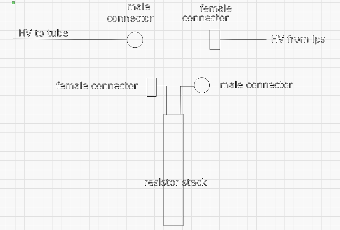
Most HV measurement probes have a resistor ‘stack’ or a long resistor. A ‘stack’ is at a substantially lower cost. With 30kv at one end, you want the other ‘end’ as far away as possible after the voltage drop.
300m ohms at 50 ua drops 15kv. Two for a 30kv drop in voltage, run through a 50ua meter. There is also an ne2 neon bulb from ground to meter, that’s not in the drawing.
I bought two meters, 50ua and 30ma. I have put the 30ma meter face onto the 50ua meter. Now it will read 0 to 30kv.
With the two resistors, the voltage at the middle could be 15kv. Acrylic has a breakdown of at minimum of 15kv/mm and a max of 22kv/mm. It’s PMMA - Polymethylmethacrylate/Acrylic.
3/4" acrylic tubes with a 1/2" hole, leaves 1/4" walls. 1/4" is about 6.3 mm. At minimum I should be safe with walls at using minimum specification of 15kv/mm x 6.3mm = 94.5kv before a breakdown.
The end piece will be filled with a clear epoxy (also good insulation).
Air gaps are not good, especially at the hot end. That’s where this stuff ‘reaches out and touches you’.
Make sense?
Remembered seeing this photo… of Lichtenberg figure in block of Plexiglas
Are you somehow going to put this inline so it’s there all the time, or will you connect it during a tube/PSU changeout? I don’t quite understand that part.
While I am using a Diode Laser, this may work for you. In Machine Settings, change from Buffered to Synchronous. Once I did this my machine stopped losing the connection in LightBurn. I’ve mentioned it to others in the Facebook Forum and it has worked for them on their CO2 Lasers. For some unknown reason, during Buffering LightBurn reconnects the signal after each Buffering when it attempts to save another grouping of G-Code. If Windows is doing something else at that particular moment. The reconnect is missed. I haven’t yet figured out how to increase the size of the Buffer, nor have I figured out exactly what size it is.
Thanks Ronald. If I run into the problem again, I’ll def check this setting to see if it makes a difference. I replaced the PSU over the weekend and everything is back up and running. Seems as though I burned the old one out.
Can you show a screen shot of this setting or how to get to it?
I went to the documentation on the ‘machine settings’ and didn’t see it there.
I didn’t think you could run a synchronous usb connection.
Also Mike is running a Ruida they are not gcode driven and store the whole file on the controller. Grbl are serial driven and can only ‘queue’ up a few lines of code in it’s ‘buffer’. This has it’s own set of issues. Especially with large ‘image’ type files.
My mistake, it is in Device Settings in the lower right corner. There is an option to switch from Buffered to Synchronous. Since switching, my GRBL based controller no longer stops mid cut.