Understanding how it works is crucial to safety with anything. Anything you can get to that isn’t insulated is safe to deal with. Meaning measuring voltages and so forth. The controller output (actually ‘sink’ current) pull the voltage to ground and it’s maxed out at about 32volts upper limit (controller.) So a voltmeter is safe for any of these checks. Mine are the standard 24 volts.
There is an anode wire to the tube and it is the High Voltage, most are wired directly to the anode of the tube. This is the dangerous end for voltage the opposite end is dangerous from laser output viewpoint. Anywhere there is HV take extra care. Most of it is safe if the insulation isn’t broken.
Resist temptation to open the HV case, generally there is little to test and few schematics to go by. Measuring the output of the HV supply requires the proper test equipment or a good medical insurance policy.
This is my power supply. The L input ‘enables’ the lasers control. Mine also has an H input. L input is active low and H is active high. The PWM output from the controller goes to IN on the power supply. With L enabled (active,) PWM will now fire the laser when it goes high.
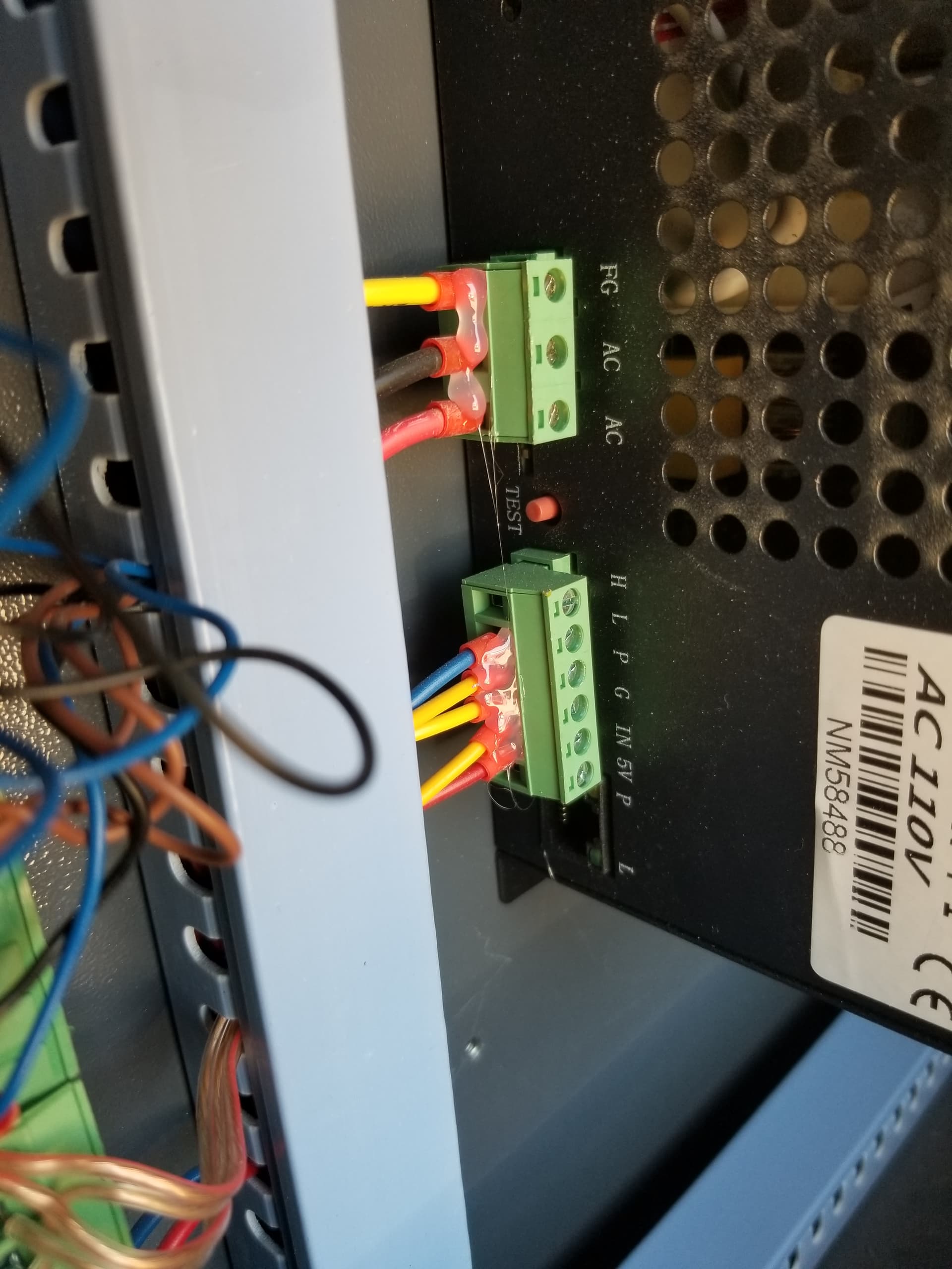
You should be able to measure either of these two inputs with a regular voltmeter. The PWM will vary from 0 to about 5v depending on the power setting.
If these two inputs are active and no lasing is happening, I think you’re at tube or power supply…
