Long shot question here - I received a new omtech 80w laser that has been plagued with x-axis movement issues. (tried swapping with y-motor driver, new mobo, and even a new motor driver all to no avail). I am trying to avoid packaging it back up and having a new one sent out but might just end up that is route I have to take.
That said, I’m curious if anyone that has one would be willing to send a photo of the x-motor driver wiring along with the motherboard wiring that leads to the x-motor driver. The motor drivers I am working with is (original) DM545C and the new one is a DM545A - trying to resolve where the 5v wire should go (along with the pul and dir wires).
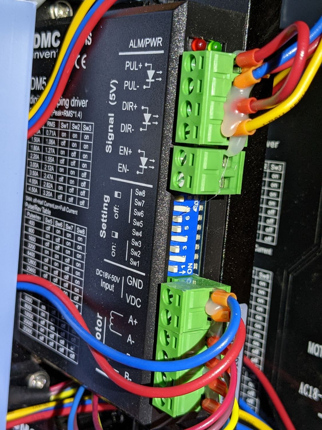
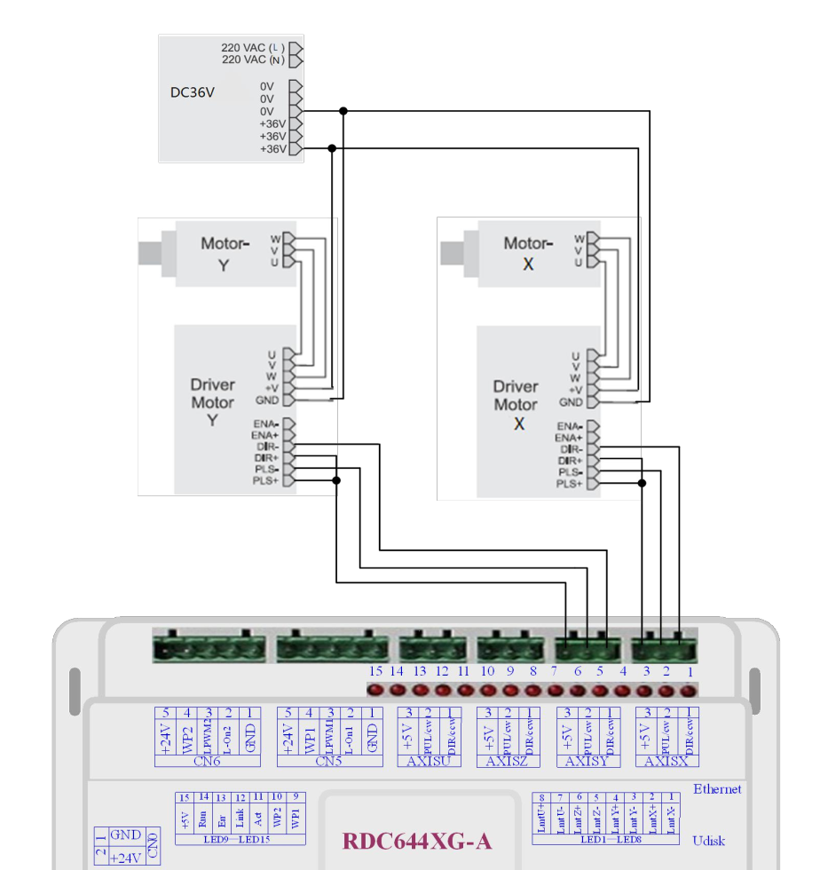
The controller’s 5V terminal goes to both PUL+ and DIR+ (it’s the short red jumper on both drivers), with the - sides returning to the corresponding controller outputs.
I’d be unsurprised to find a wiring fault in the cable between the Y axis motor driver and its motor, unless you have already ruled that out.
Given what you’ve already done, however, the problem is most likely a simple-to-fix mechanical misalignment. At least after you find it, anyhow.
The motor is in the middle of the back where it turns a pair of loooong shafts driving belts along the left and right sides of the frame, with a remarkable number of flexible couplings, set screws, grub screws, pillow blocks, pulleys, bearings, clamps, and general gimcrackery in between, plus two more pulleys at the front of the cabinet.
Verify all of that hardware is firmly mounted to the frame, the belts run true in the pulleys, and that the gantry moves smoothly on its linear bearings.
Check all those myriad screws to verify they’re snugged against the flats on the shafts and that everything turns as a unit.
Any looseness will let the shafts turn separately, which will rack the gantry and cause motion problems:
In fact, I’d be unsurprised to find the gantry arrived racked, so you may need to loosen the flex couplings at the motor to let the shafts turn independently, move the gantry all the way to the front to align it, then tighten the shafts.
Check your motors and ensure the motor drivers are not set for too much current…
I was working on mine and the motors were too hot … checking the motor specifications and the motor driver settings I found the factory had set the drivers to twice the current limit of the motors… that gives you a good feeling…
Thanks for the suggestion - I’ll have to keep that in mind when/if I can get the current issue resolved as I’m not even able to turn it on without the x-axis movement producing a grinding sound and staggering back and forth. (My understanding is the machine should “home” on startup to one of the back corners).
Ok, wow, thank you so much for the photos. That is NOT what mine looks like at all… so there are three out of the motherboard. The Red, Blue, Yellow - where the wire in position 3(5V+) feeds PUL+ and jumpered to DIR+… thank you, I’ll try that configuration in the morning.
That suggests a different and non-mechanical problem: the acceleration and speed for the X axis seem be too high, so the motor loses sync with the pulse train commanding it to move.
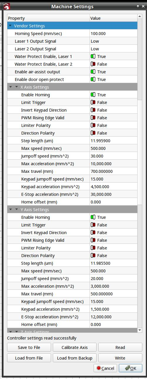
After you’ve verified the mechanics move smoothly by hand, compare the X axis acceleration and speed values with the Y axis. Look for one too many zeros (50000 instead of 5000) or a random-ish value.
Check the homing speed, too, which should be around 100 mm/s.
All those are in Edit → Machine Settings → Vendor Settings:
To a good first approximation, all tabletop diode “engraving” machines seem to arrive with, shall we say, highly enthusiastic optimistic speed and acceleration settings that may have worked once on a clear day with a tailwind.
Wow, this has been an issue for about 4 weeks and thanks to the photos from @ednisley I have resolved the jitter. Interestingly, omtech sent out a DM545A to replace the DM545C - wring up the A with the jumper solved the problem. I suspect the C must have been initially wired wrong and a little surprised/bummed that omtech tec support didn’t spot that at the outset. Also interesting is that the C is wired exactly the same for the y-axis motor driver and the y-axis works great.
Thanks all for the suggestions, now to go calibrate.
And a spare motor, spare mother board and spare controller as they sent me all of those things to try and diagnose the issue… I dunno why they didn’t spot, or ask about, the wiring issues at the outset. Also, the y-axis is wired up exactly the same and runs smoothly. Just did a test cut of a circle and square both of which look perfect (though I don’t have my glasses on).
Re: the dip switches, both the x and y driver switches match also matching the new replacement driver
Again, thank you! (Really didn’t want box this up and take delivery of a new one)
Wow, talk about throwing stuff at the wall to see what sticks!
Because those are impossible!
For whatever it’s worth, trust in wire color codes is a Bad Idea™:
I have no idea why “the same wiring” would work on one axis and not the other, unless the initial fault fried the poor driver. I find that hard to believe, but at this point any assumptions seem entirely unjustified.