Hey all,
I just upgraded my omtech k40 with a monport nano control board but I’m having problems with the machine being over powered. in lightburn when I run at 0.1% power, the machine is pulling about 4mW and is a lot more powerful than it was with the previous controller. And as far as I’m aware, it shouldn’t even fire at such a low setting.
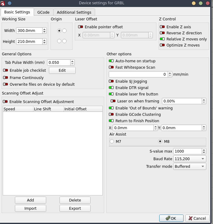
I’ve verified that the $30 value and the S-value max value are aligned and that seems to have not corrected the issue. I suspect the problem lies in my other $ values such as $31 $32 or $33, but I don’t have a reference for what these should be with this setup. I’ve also heard reference to a potentiometer of some sort, but I don’t believe my machine has one to adjust.
Yes I thought so but nice that you have an ammeter. That percentage versus power ratio is very wrong
I’m a little surprised that you haven’t received an installation guide for your new controller on the K40. A few years ago I changed my K40 controller to a Mini Gerbil v2 from Awesome.Tech. On their site there is a fine explanation for setting up ver. 2 and ver.3. You might find some input there. You are also welcome to get a backup of my setup, but I don’t know if it can be used directly for your controller. (I no longer have my K40 but was very happy with my first CO2 laser)
If you still have it, that would be great, thank you! I’ve been playing with my $ settings and have noticed some strange behavior. Like I don’t seem to be able to modify $33 which should be the PWN dutycycle/frequency, it’s stuck at 1hz. I’ll do some more troubleshooting but probably reach out to monport to see if they can tell me what’s going on with that.
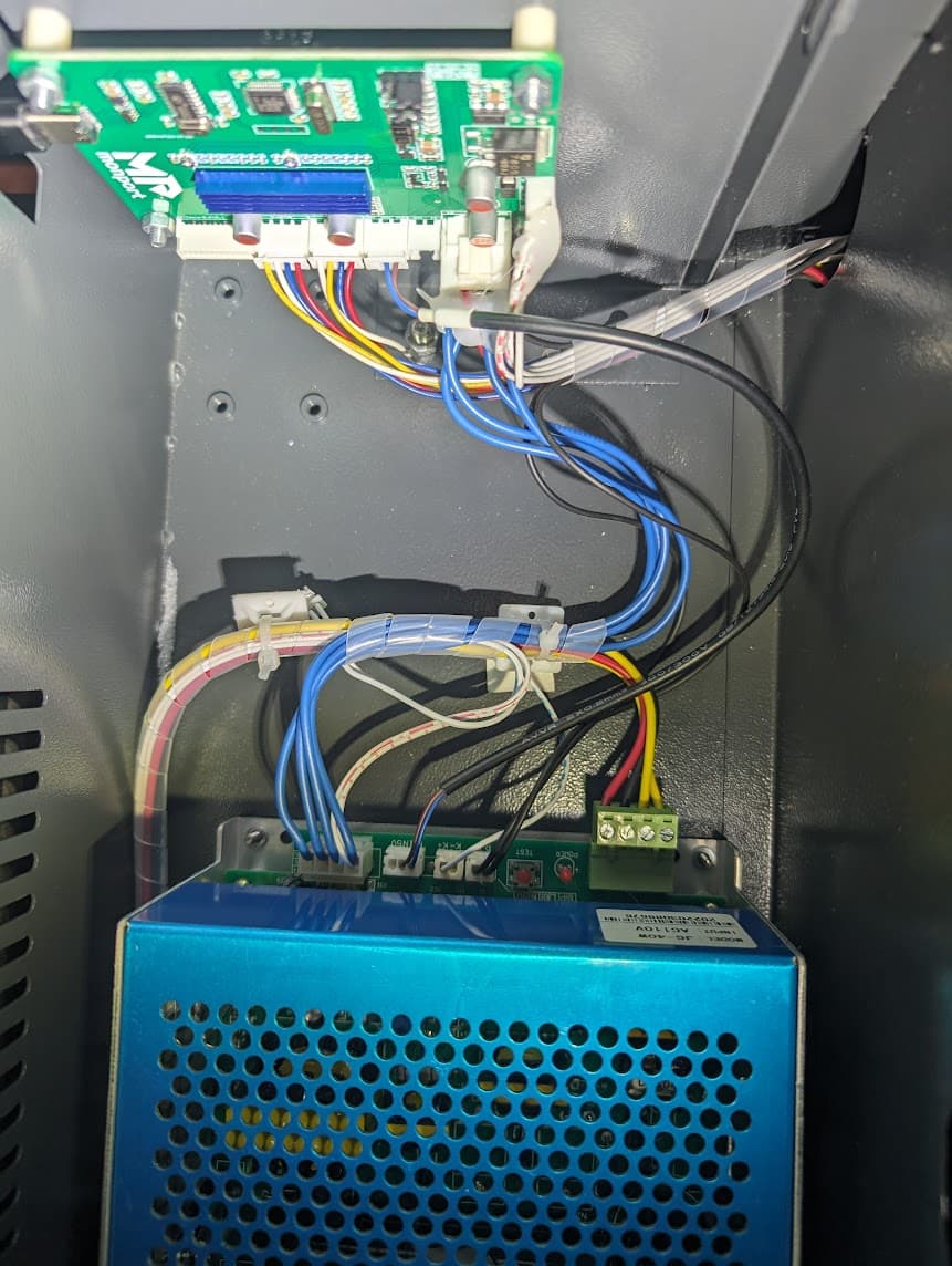
It’s this control board here. It’s able to connect and interact with lightburn, and aside from the power control it works perfectly. I’m new to this space but it wouldn’t surprise me if there are several boards called “nano” which can cause confusion.
oh good idea, I figured the duty cycle would vary, not the voltage, but sure enough it seems to be the voltage. After doing some tests I saw that I was getting 2.8 volts between in and g coming from the controller on the cable that goes to the board attached to the power supply when at 50%, then somewhere around 1.2 volts on 20%, an around .5 volts on 0.1%, I figure there could be a problem with my multi meter, or it’s not reading the correct voltage since i’m not getting those readings while the cable is actually attached to the power supply board and there’s no load. However this does tell me that it is varying the voltage in correspondence with the settings in lightburn.
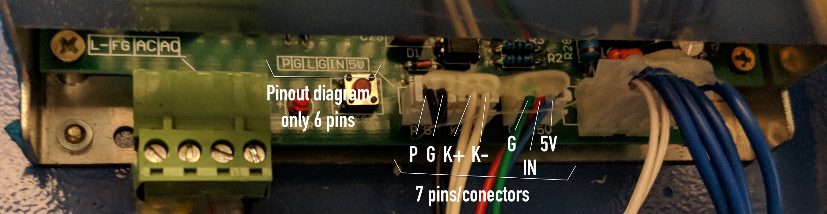
I’m going to borrow this image from another forum since they took the time to take and label photos of the board that my machine has.
Right now I have the case open switch connecting p and g together. K+/- is still connected as it was from the factory, but of note is that only the K- wire is actually inserted into the connector, I think this just relates to the test fire button on the control panel, so I’m not particularly concerned with it. Finally I have G connected to the ground of my control wire harness, and IN connected to the positive, 5v is left empty on the connector I received from Monport.
I noticed while testing that if I left the G/IN/5V connector unplugged entirely while reading voltages coming from the control board, the laser would still fire, I’m unsure if this could be an indicator that there’s actually something else controlling the laser firing, or if it is just because there was a floating voltage on the in pin since nothing was connected.