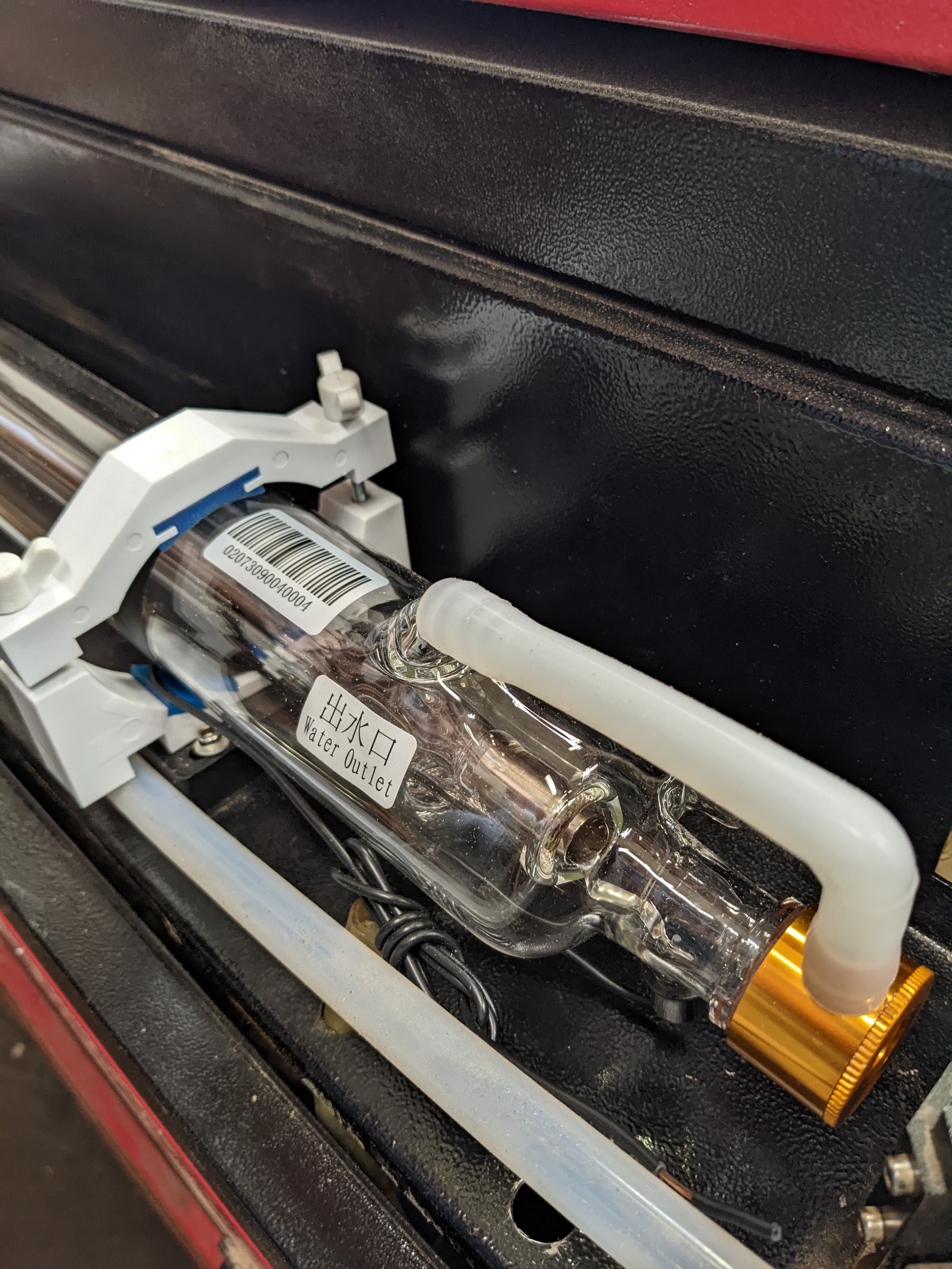
- Model CR70 : Power 60-80W,Length 1250mm ,Outer diameter 55mm
Size: 60-80W L1250 D55 CR70
As for getting to the pot, I have some jewelers screwdrivers I can use, cut them down if needed.
Size: 60-80W L1250 D55 CR70
As for getting to the pot, I have some jewelers screwdrivers I can use, cut them down if needed.
So, if I want an 80W tube, and I get the 60W that you received… this make no sense to me…
There is a 30% increase with no difference in the tube…?
Thanks for the link…
You’re operating with no view, I purchased these for adjusting so I could eliminate the possibility of a short, I doubt there’s any hv around it…
https://www.amazon.com/gp/product/B07WCV3B2M/
Good luck
![]()
Me neither, but I’m going with this is 60w and someone in marketing decided 60-80 sounded better. “Hit it with 21mA, you can get 80?! 60-80 it is!” Lol
Drive a car out of the back of a C-130 Transport and you can get upto 300 MPH out of it.
I have bought tubes from www.lightobject.com they only carry high quality tubes. Looks like you have a 45w tube (880mm). You must have a K40. I would look at what temperature you are at when you burn.cut…that will kill your tube.
I only saw one mention of manufacturing date. Its my understanding that these things have a shelf life, so if your tube is new, but been sitting for a few years, it could have lost a gas charge. Especially depending on brand, the quality of seals and connections is going to vary, and throw a variable into the mix.
When I was active in the FSL groups and doing a lot more buying, it was normal to see downrated tubes. Full Spectrum sold us a 40w machine, it had a 45w tube in it. When we replaced that tube, I ordered a 40w replacement (couldn’t find the 45) and it was actually a 35w tube. Theres rated and actual usage.
And on that, one of the reasons that I think we get longer out of a laser than others is because we try to run them max of 60% power. Occasionally I’ll run something where I need to blast 100w to try and punch through something crazy like 1" thick wood at 3mm/s, but its rare.
Bought a china blue 50W machine. The tube is 880mm and reads 44W with a Mahoney meter. Cutting acrylic I run it at 80% about 20% to 30% of the time. The machine was built at the end of 2020 and the tube was built in Jan of 2021.
Mine came with a ‘test’ sheet that stated maximum current was 21mA… that’s where the lps is set.
I have more than 330 hours on it… according to the Ruida.
Of course, at 880mm it’s not going to be 50W… Probably should have complained. It did come with a 60W lps.
![]()
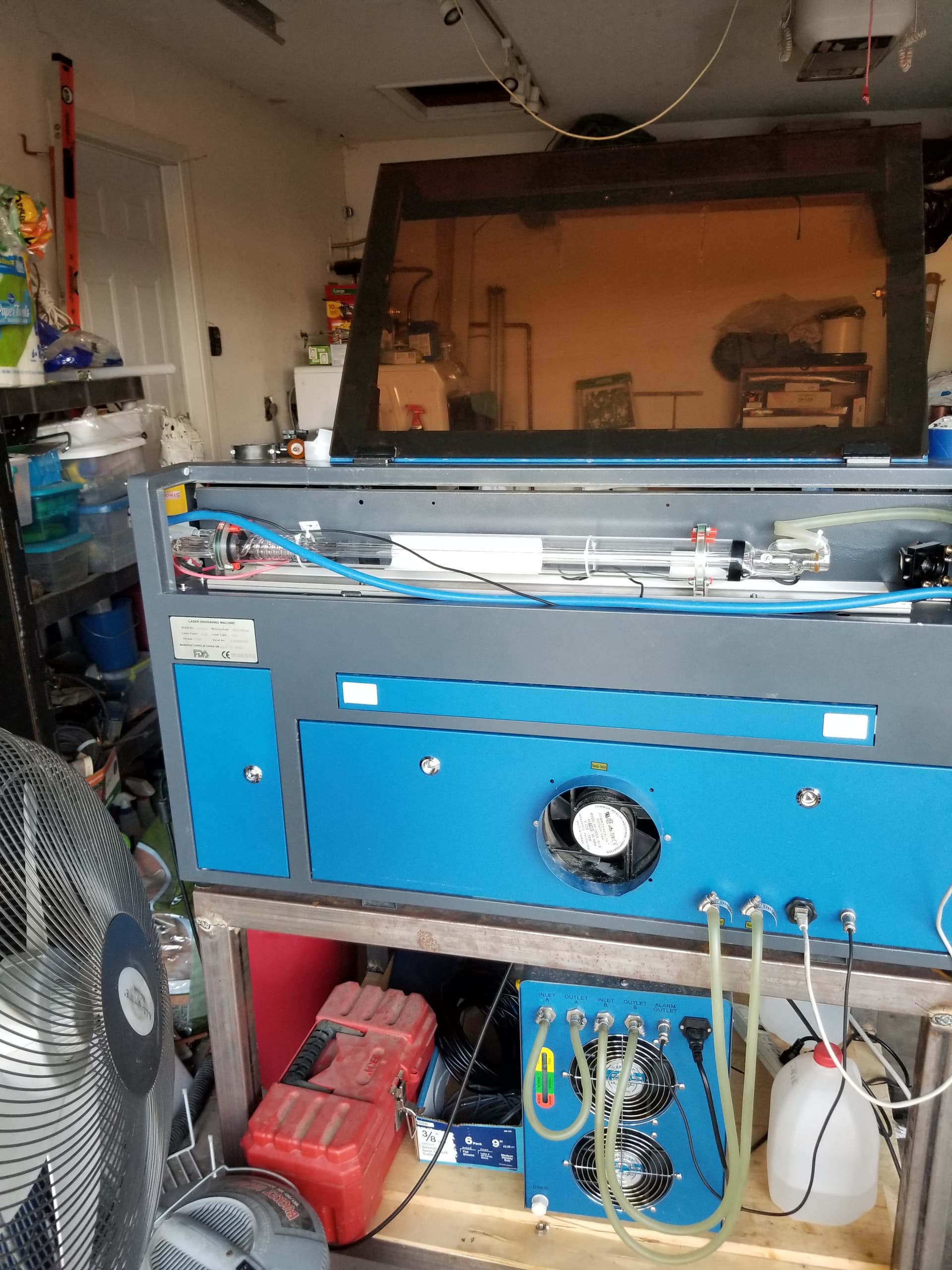
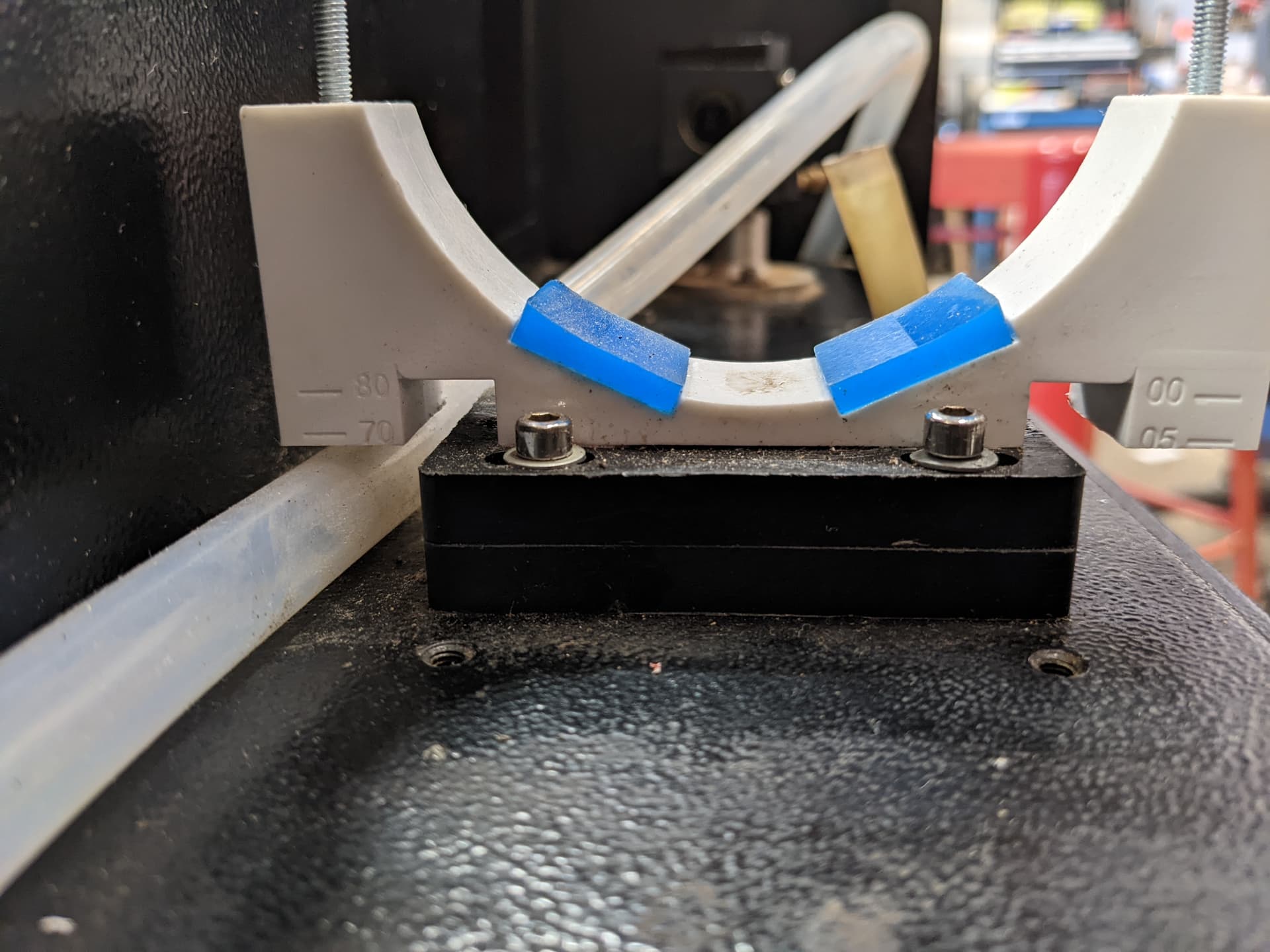
Welp, got all the parts in but didn’t realize the new tube mounts were so thick at the bottom. They raise the tube up way too high and they’re as low as they can go. ![]()
I was suspicious about the tube mounts… There isn’t much room in there…
If you raise m1 you will have to raise them all.
Russ Sadler makes a tube mount… I have it in my machine and I think it will hold the 55mm tube in your machine. Might want to drop him a line…
It runs the entire length of the cabinet and m1 attaches directly to the same frame.
Here’s the anode end…
Cathode …
The whole thing…
tube clamp MK2 BUILD DATA.lbrn2
Let us know what your solution is…
Good luck
![]()
I kinda need to be back up and running, so I combined the two mounts
PXL_20221025_222829974.MP
Roughed up the surfaces, hefty amount of super glue, and I can use them like handles to shake the machine. Pretty sure they’re solid. ![]()
Had to secure the front mount a little weird because the screw kept slipping out of the insert.
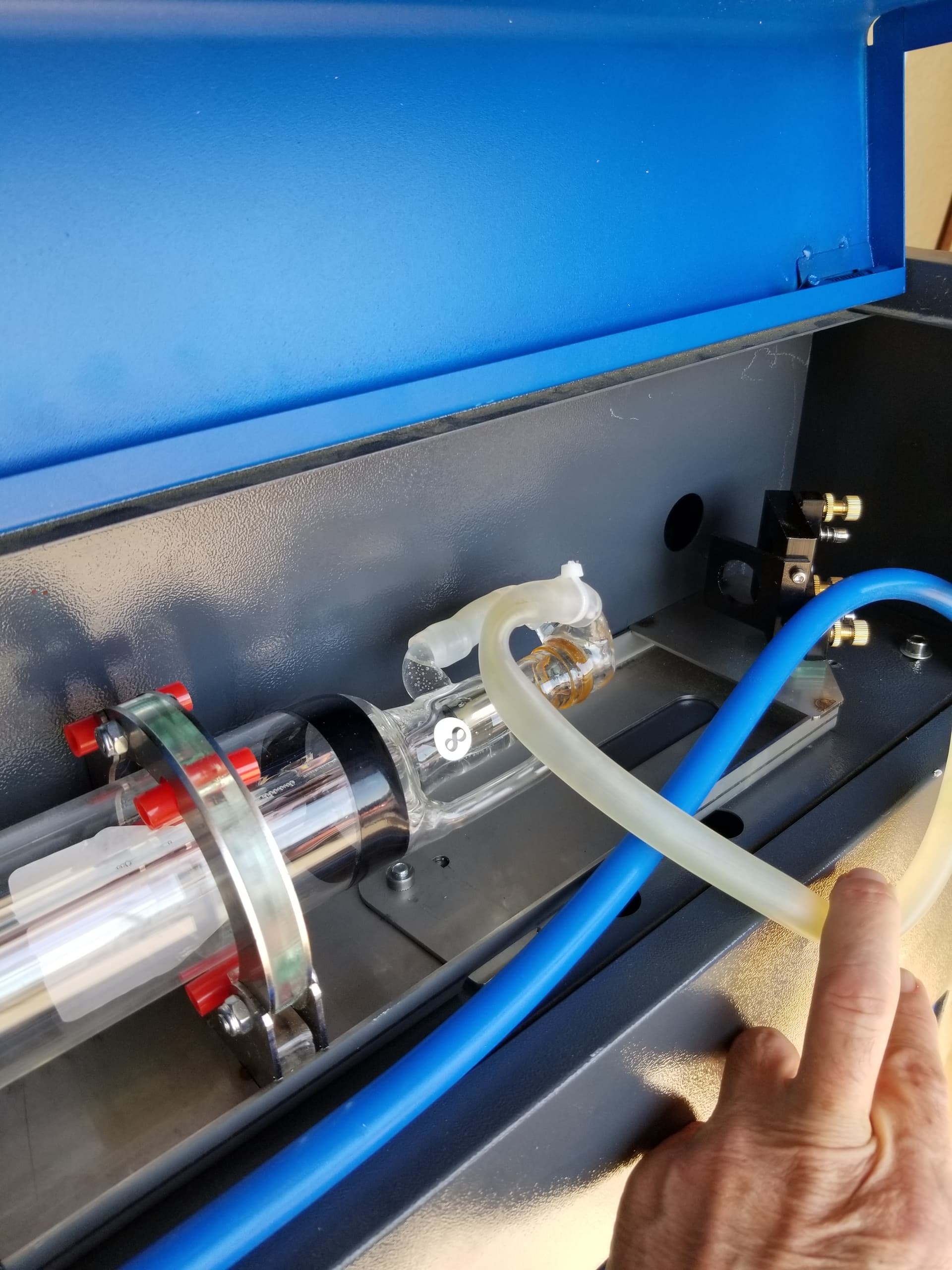
Then there was the fun of getting a really stubborn bubble out from the front. Can’t just lift the back of the tube since this tube extends out of the machine. (Yes, it’s protected ![]() ) Ended up just tilting the whole machine.
) Ended up just tilting the whole machine.
Next upgrade, a “clean room” for it. (Shop is way too dusty)
Thanks again, everyone!
so you can ‘burn’ stuff in a ‘clean room’? ![]()
![]()
When starting up my lase, if it has not been used for more than a few hours, I always have a micro bubble, foam-like air encapsulation, in the same place in the tube.
I always have to press the rubber hose a few times to get them out.
(And yes, my tube is correctly mounted)
So I can keep sawdust out of the laser. ![]() Building a large box with an inline fan pulling air though a set of filters. Shower curtains over the front, exhaust runs out the back. Positive pressure will keep the majority of dust out.
Building a large box with an inline fan pulling air though a set of filters. Shower curtains over the front, exhaust runs out the back. Positive pressure will keep the majority of dust out.
This was a big one, maybe the size of a nickel. Wouldn’t budge.
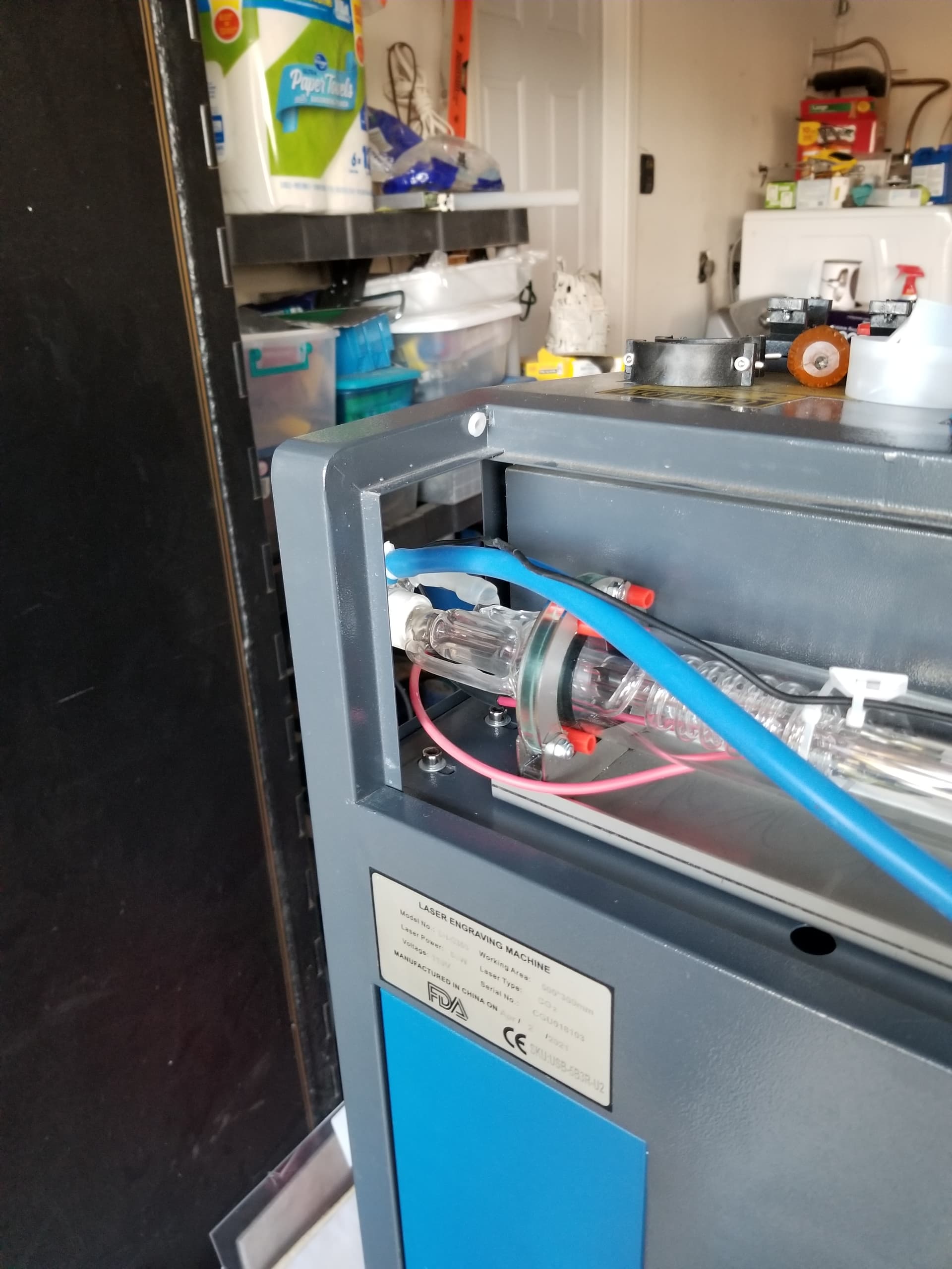
Just about to install a potentiometer on/at the power supply to dial the tube in, rather than deal with trying to get to the one in the power supply.
You need to set the current at the lps.
If you use an external pot like a K40 wired as an analog voltage to the IN of the lps you are not controlling the tubes current…
You will also lose one of the main advantages of a good controller, pwm and ‘Laser on’ controls, the two real control lines to the lps…
![]()
Are you certain about this? I’ve seen C3D folks using both analog pot to control overall current range while still using PWM to control power within that range. But I may have misinterpreted what they were doing.
Maybe I’m missing how controlling the voltage to the IN wouldn’t ultimately control tube current. That’s the only method of control I believe most K40 users with the default boards are using to prevent overcurrent on their tubes.
The current draw of a co2 is whatever the supply can produce when it lases. When you change pwm you are changing only the average power reading on the meter.
Because most pwm are square wave you can figure that if you set your pwm to 50% the meter will only read 50% of the max current.
Same with a voltmeter on the same pwm, at 50% with a ttl (5V) signal the meter will read 2.5V not the 5V, because it’s on at 5V for 50% of the time… The meter is getting 5V or 0V, never 2.5V… which do you believe?
When they ‘test’ your tube, they set the lps supply to a know maximum current limit for the tube, such as 10mA. They then test the tube at different pwm rates and can give you a wattage rating.
There are different opinions about this, but when I can physically see it turn off/on on the material, it’ll be an uphill battle for them to convert me … I am open to change…
We know there is correlation to current and output power, but there is a balance of how much power to it’s usable life. A tube is a ‘negative resistance’ device, meaning an increase in voltage doesn’t directly correspond to a proportional increase in current.
Hope this make sense…
![]()
Great info Jack, thanks!
Getting to the pot wasn’t hard after I pulled the power supply off the “wall”, and there’s enough play in the cables to keep it connected and have easy access while adjusting.
Okay. You’re basically saying that the tube draws what it can from the LPS whenever fired and for the duration as specified by what I’m assuming is PWM frequency. By that token the only way to limit true current is by limiting the output current of LPS.
I think I’m fine with that technical aspect of it but I’m curious then if it’s the peak current as provided by the LPS that’s the issue with accelerated degradation or the sustained current. For most users PWM is the only method by which power is being modulated and laser manufacturers themselves only say things like “don’t use power over 70%”. So wouldn’t that imply that the current value displayed on the ammeter or controlled by the pot is effective in limiting tube damage?
However, I could see a scenario where peak current rating of the tube must be higher than the current rating of the LPS to work safely. In that case a tube rated for peak 20mA but driven by an LPS sending out 30mA even with PWM duty cycle at 66% would be degrading the tube. I’d always thought that a higher rated LPS than necessary was simply allowing for headroom but if the former is true, that could imply that a higher rated supply is potentially damaging to the tube and in fact, a lower rated LPS could more safely drive a tube if tube longevity were the primary goal.
Is it certain that the pot on an LPS is actually reducing current and not actually just modifying duty cycle?
In the end, yes… That’s how tube manufactures test them, they set a maximum current for the tube at the lps and test using pwm at various levels to give you watts out…
What initially starts the the tube to lase is the hv potential virtually no current … that excites the nitrogen. As things start to lase it starts drawing more current. When it’s lasing properly as designed it’s drawing full current. I’m suspect you could get 200W out of a 50W tube by allowing high current flow… however the usefulness of the tube will probably be short lived…
I’m sure there are limits on size/power/physics that limit this, but the idea seems to hold.
I have a 60W lps with my 880mm tube. I think it has a faster than normal response that I attribute to the lps. To have a fast enough response the hv must climb much faster for a 150W tube compared to a 50W tube.
Keep in mind that with an led laser the pwm directly controls the laser, at least on my first laser with no electronics…
A co2 tube driven by a pwm based on the Ruida, that has a 50uS period (20kHz) can’t expected the tube and supply to respond fast enough to directly control the tube cycle. The lps I’ve seen that do specify a response time is 90% of the placarded hv <= 1mS or within 1/1000 of a second…
That’s 1mS - substantially slower than the 50uS period of the Ruida pwm.
I’m no ee, but my examination of the schematics show the IN input being converted to a dc voltage that controls an oscillator which drives the switches generating the hv. In the primary side of the hv transformer is a ‘current sense transformer’ that generates voltage proportional to the primary current. This is where the lps current is adjusted…
On K40 types, that have a pot or a voltage supply to the IN terminal. This runs the vco (voltage controlled oscillator). The pwm is applied to the ‘laser enable’ and modulates the enable input.
It’s actually a quite clever way to implement it on a normal lps with Laser enable and a pwm control voltage, with only one control line… the other line is handled by the human hand with the pot…
When I was playing around with ‘speeding’ I set my period to 1mS, 50% power. Made a box, fill with a speed of 500mm/s. I duplicated the box but set it to 1000mm/s, then again at 1500mm/s
At 500mm/s I get a brown line. I am moving at 1/2 the pwm period/mm.
At 1000mm/s I get a dashed line, 1/2mm burn, 1/2mm no burn.
At 1500mm/s I get a dashed line, with about 1/3 burn, 2/3 no burn.
At 1mS period (1kHz) I can see it turn off and on… that’s pretty convincing… ![]()
The surprising part was the damage to the material at each of the speeds were pretty close to each other even by 50% speed change.
Which do you believe? The voltmeter on a 50% ttl pwm signal is really reading the voltage of 2.5V or it’s really at the 5V you know is there?
It’s 2.5V over time … just like the ‘imagined’ laser power… ![]()
I’m sure that a relatively larger lps isn’t going to be damaging and could make the overall system faster… just like everything I’m sure there’s an upper limit. One of the issues is can you control the current to a proper level.
![]()
This topic was automatically closed 30 days after the last reply. New replies are no longer allowed.