That was the plan, on day three I got there.
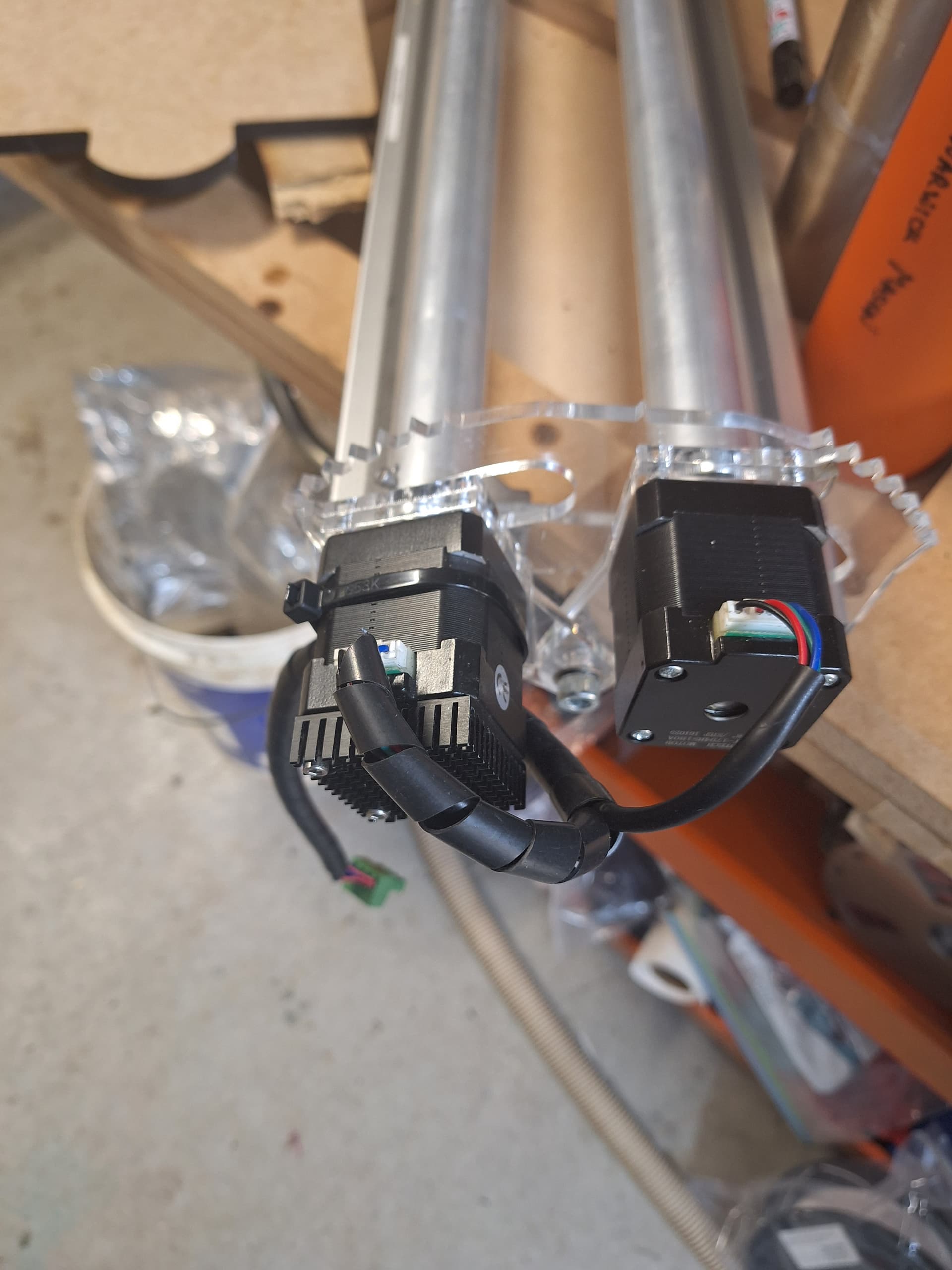
As I did not have a belt spare I decided to use two small nema motors run off the same drive.
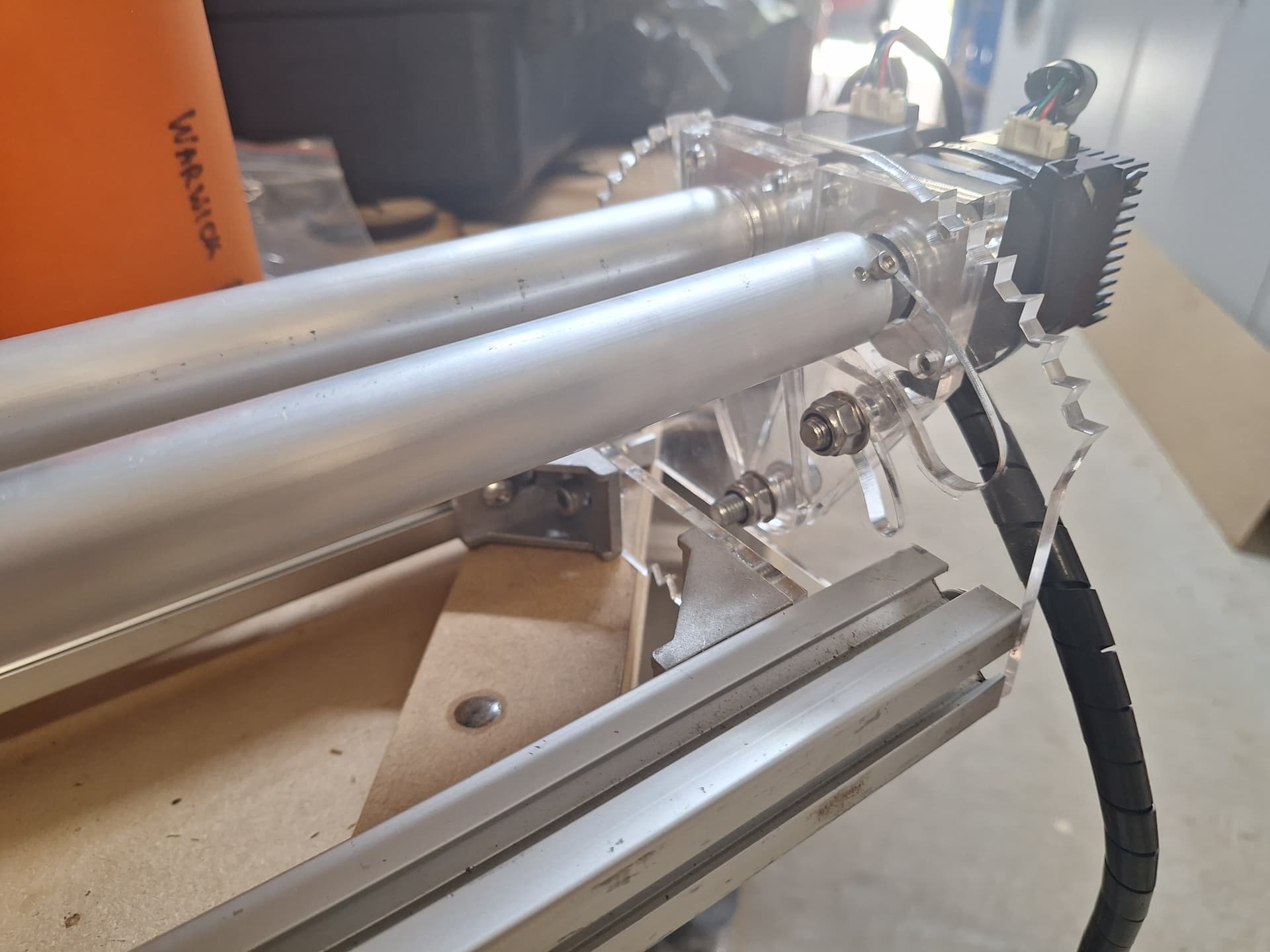
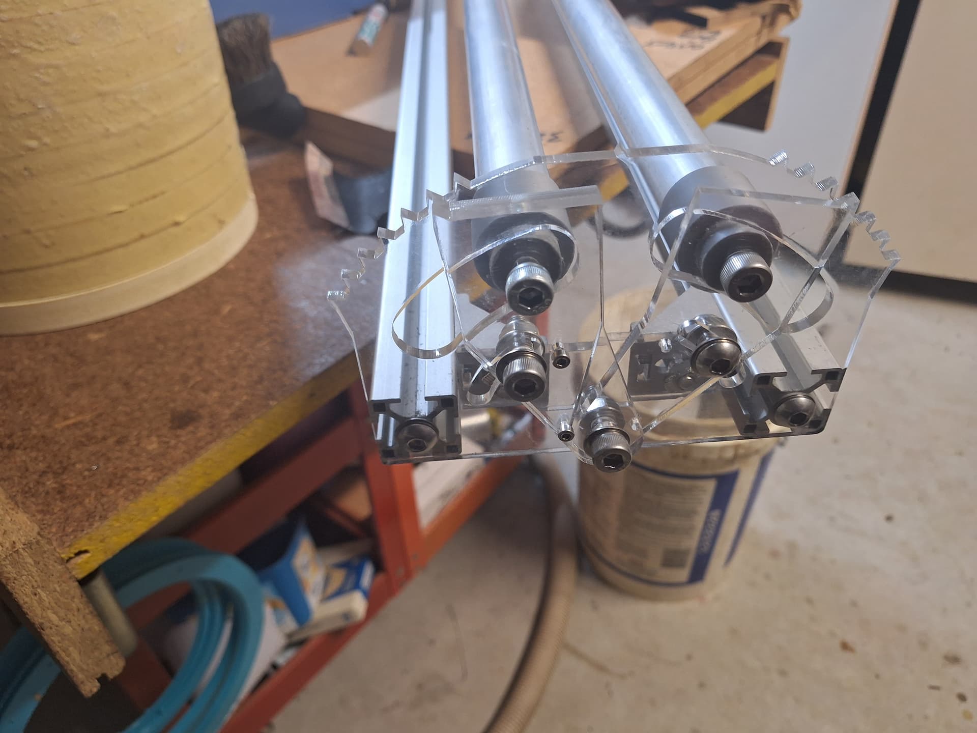
Attached is the lightburn file for acrylic cuts. I used 4.5mm, 30 x 30 square extrusion tapped for 8mm and 25mm ali tube for rollers.
3D the four fittings to match from steppers to tube and at the far end tube to bearing secured by 8mm bolt.
With this arrangement I should get close to 300mm diameter jobs in. Also I can place multiple small jobs in line even if I 3d print a distance place holder affixed to the tube.
300mm x Pi = 942mm my Y axis would need to travel , I have 925 available.
My Y axis is switched to “disable”, earth to enable pin and at the same time 24v is powered to the rotary axis thus enabling it.
Direction and pulse(step) are linked in both drivers.
updated lightburn file with cross bars, these were designed to go between 3030 extrusions and have an arrow showing the centreline, engrave a line on wasteboard and set these to it. Rotary roller.lbrn2 (130.0 KB)
Typically the Enable inputs to stepper motor drivers are low-active, so you may want those the other way around.
The control inputs are generally powered from the +5 V logic supply, rather than the motor supply, and need only a ground / common connection when active.
If you’re wiring the Enable input with the optoisolator’s cathode side grounded, then switching +24 V to the anode (*) to turn it on, mention that whenever anybody else looks under the hood, because it’s definitely unexpected.
(*) Through an external current-limiting resistor, because the internal resistor is specified for +5 V operation.