Opportunity for improvement in offset fill

Dear People.

I have noticed that the off set fill produces artefacts due to its spiral movement compared with normal fill that can use left to right on the X axis.

Using a cheap Atom Stack A5 Pro moving in both axis at the same time produces errors in movement due to more mass movement.

Simple solution allow the user to pick offset fill but then use left to right X axis movement only per bit of art/letters. If you allowed the use to pick this option then we would not get poor quality finishes.

Please stop using spiral as this is not good for quality output on cheap lasers.

Its a very simple development request. I think as a software engineer this is a simple thing to do. In software when we do a flood fill, we can be made to do left-right very easily.

Please allow people with poor quality machines to just work on the X axis with the lest amount of mass to avoid spiral issues.

I also found this issue with CNC with wood going against the grain when two axis moved at once. It was always better to go with grain, left to right, it produced a much better finish.

Simple solutions easy to implement.

Please Thank you in advance.

Do you mean… A normal non offset fill?
What you might want to do is break the text apart and fill 1 letter at a time to improve time.

Not ideal but should do what you seek.


You guys are very fast in replies.
KUDOS for this.

Off set fill uses spiral on my copy of software.

I must have made an error I cannot see offset fill option to use left to right on X axis.
If I use Y axis more mass is moved, meaning more chance of errors at higher speeds.

$0.02 worth

The point of the offset fill, is it starts from the center and tries to reduce as much as possible any non engrave motions - and at the same keep the constant speed.
Avoiding therefore having to contend with acceleration and deceleration, M4 laser modulations etc etc

The moment you go from spiral to left-right or up and down you are in the realm of a normal fill mode - so you simply change to Fill mode. And you change the angle to use the axis you intend to. 90Âş will use Y motion - 0Âş will use X axis.
You lose all benefit of the offset fill in speed and constant power though - in fact you can see the it by observing above the traversal moves diffeerence

All the red movement lines are wasted on decelerating > stoping > turning around > accelerating

1 Like

Edit side note

On offset fills, I found - on diodes - that as you pointed out need to be extremely fine tuned belts/Drive wise to be accurate - to defocus the laser just a little bit

Let’s assume your focal range is 30mm, I would lift it up or drop it 1-2mm so the focus is a bit off, compensating of course with more power.

On offset fills this little focus loss widens the beam and covers a lot of the little offset “issues”.

But then fill mode does all letters at the same time, see movement between letters.
I would like the option to use left to right on each letter with out making it its own job.

Yes if i do one letter at a time, true.

This is a very easy fix, it combines both fill & offset fill.
I try like many to reduce movement when i can

I think many users would like better optimization of offset fills and stop this spiral issue leaving artefacts in the design output.

Laser mass is important on cheaper machines like I use.

Plus the precision in floats may effect the coverage, thus leaving artefact’s when curves in the spiral used.

Thank you for your time, please think about it a little more, don’t just give an opinion of the top of your head.

I don’t think you understand my point here.

No disrespect meant.

No disrespect taken.

Notice this settings pelase:


2 Likes

Great thanks, I did not see that at all.

Great support, thank you so much.

My BAD.

Amazing it works.

KUDOS

1 Like

Under the advanced tab, you can select FLOOD FILL. That can sometimes save you time, also.

I have to say, what great support from staff & user base this forum has.

So happy to use your software and to get to learn every day here.

Every time i mess up with my mistakes I learn something new.

Thank you all very much for your contribution and help.

-------------

Ceramic using Norton White tile method.

Example on slate, three panther kittens.

Iconic lady
.

2 Likes

This item was not addressed, so I butt in. Artifacts are not due to the spiral movement.

Play with DPI, or Line Interval (they are the same thing). At 50 DPI (.508mm interval), you will see artifacts (unburned areas) in the text with glory. At 318 DPI (.08mm) (highest practical DPI for a diode), they will not appear because the burn paths are nearly touching for most diodes.

I defocus for most everything but cutting. Kind of blends things in.

2 Likes

Dear Mike

With my cheap Atom Stack A5 Pro, the movement with spirals is an issue as i stated due to head mass. My flimsy system cannot move my wobbly head accurately.

In my opinion, the Spiral motion can if you look at the maths be different coverage/output to left-right movement. Its to do with math accuracy making curves out of straight lines and types of fill of the said pixels… After all pixels are integers and the curve is an approximation of a float. When we look close at the outputs we can see a very slight difference.

You are however correct with DPI .
1mm / 0.08 is 12,5 laser dots.

Yes I agree it should be 25.4 * 12.5 = 317.5 per inch but 318 is the best fit.

I did actually do this calculation after i wrote this issue, i picked 254 to approx. get 10 / mm. It reduces the pass time for completion of the job and i have been fine with its output until i tried off-set pass.

I also did think it could be a Nyquist-Shannon_sampling_theorem issue.

Support did give me the correct solution. I was using the interface incorrectly.

Dear D Kallenberger

Yes your correct defocus can also work to fill in the digital errors, but i feel this is a fudge / workaround.

Please read my conversation with Mike.
He makes a good point with DPI.

I feel the issues where both DPI & math combined…

$0.02 worth

Best regards

Mark

Dear D. Kallenberger,

Thank you for your input.

Defocusing the beam spot is indeed a viable solution.

However, there are a few caveats to consider:

  1. Defocusing reduces the spot power. For instance, my 5-watt laser would be underpowered if the spot area increased fourfold. This would limit my ability to engrave on slate and ceramic tiles effectively.

  2. Users with a 100-watt CO2 laser likely won’t encounter this issue and won’t need to rely on this workaround.

  3. Defocusing might cause banding in your output due to potential overlaps between lines, which is something we typically try to avoid.

$0.02 worth

Best regards,

Mark

It sounds like you want Lightburn to compensate for the shortcomings of a low-cost hobby class machine. It would not be fair to expect Lightburn to raise your machine to a production level of performance.

“…to avoid a type of distortion called aliasing.”
If I remember right, this has nothing to do with parallel straight lines. Aliasing is the artifact of digitizing diagonal lines. Unless you set your scan rotation to something other than 90 degrees, Nyquist does not apply here.
Make sense?

2 Likes

Works for me, but I’m not a perfectionist.

Dear Mike Hembrey

Never have I requested compensation.

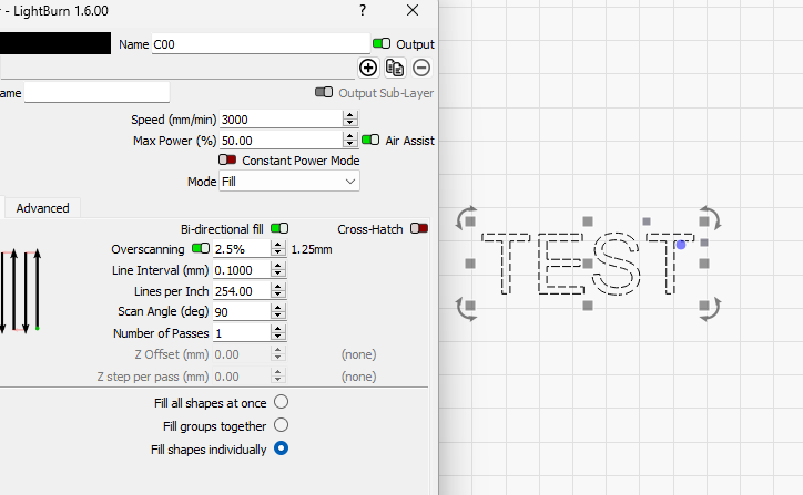
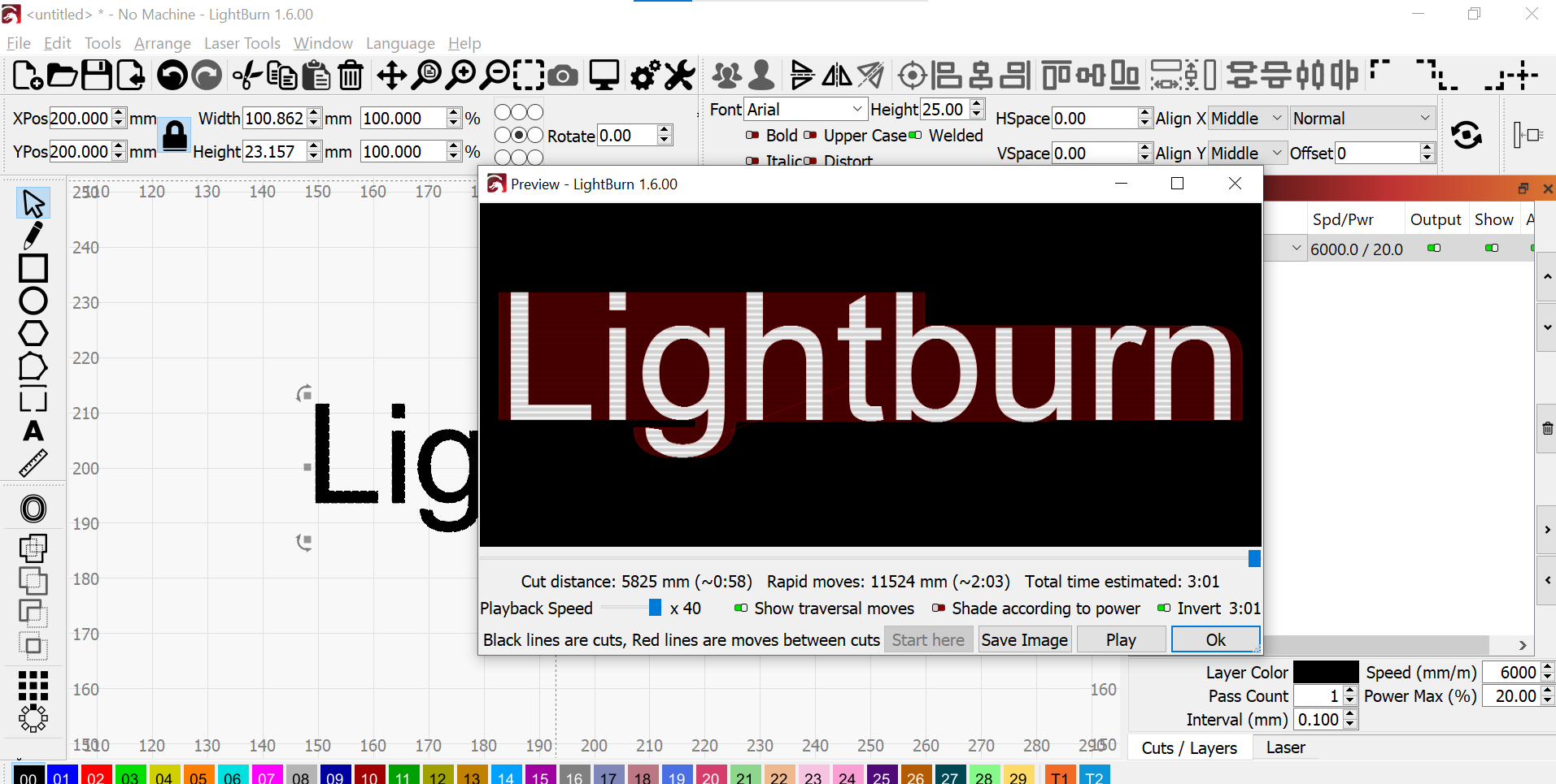
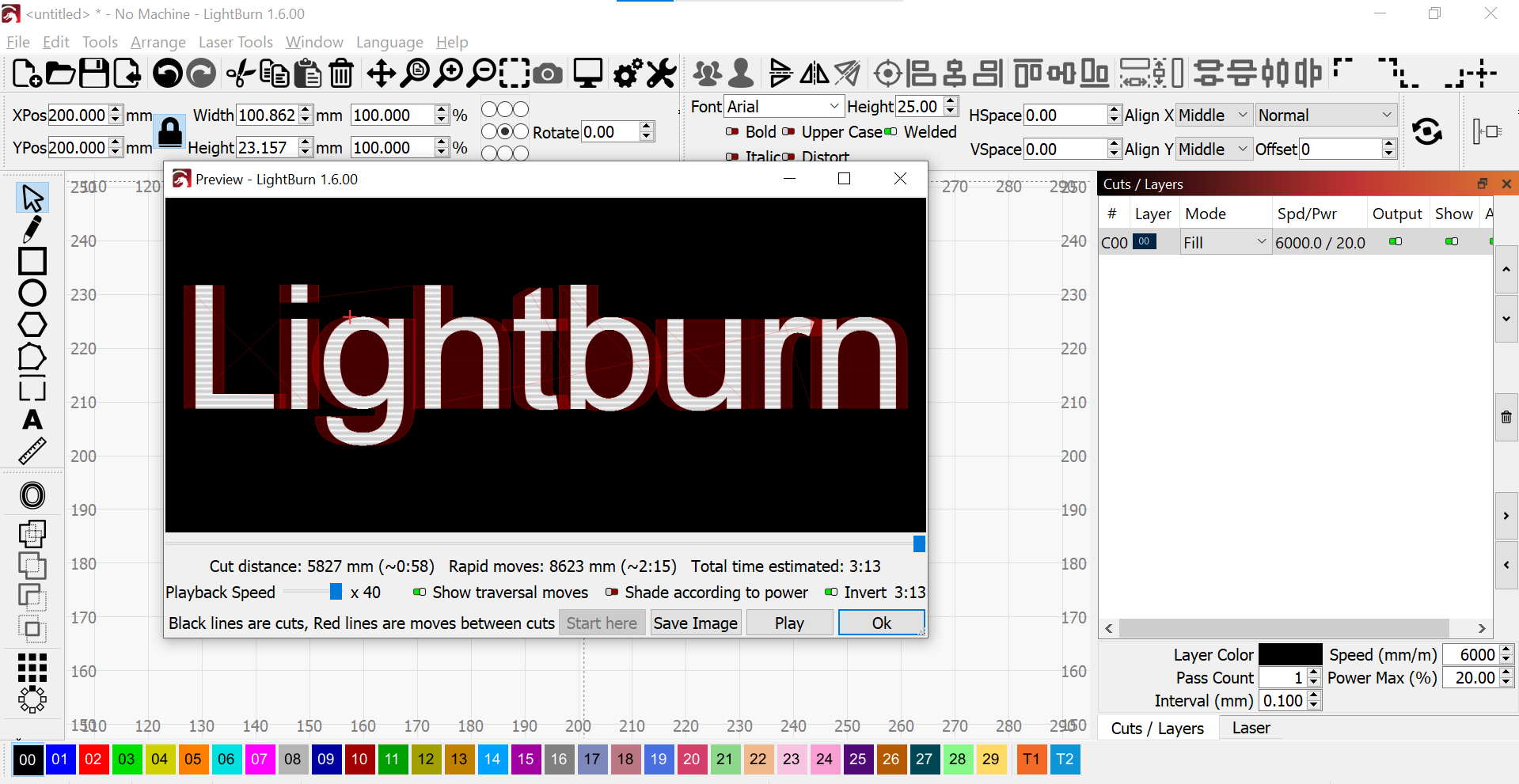
If you laser head wobbles, move slower.

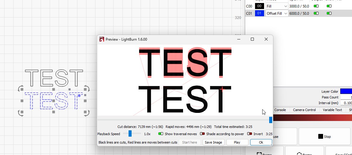
Movement in the X axis alone produces a better finish then movement in both X & Y axis on cheap machines due to poor design & build.

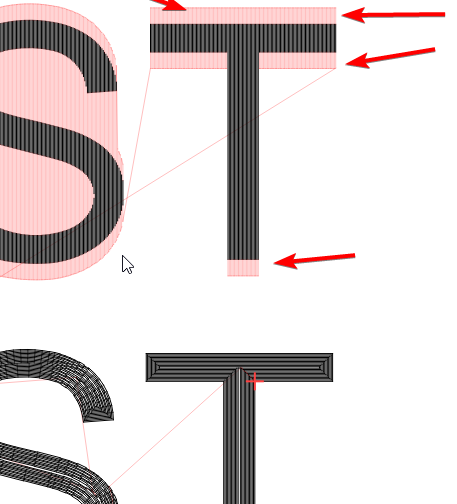
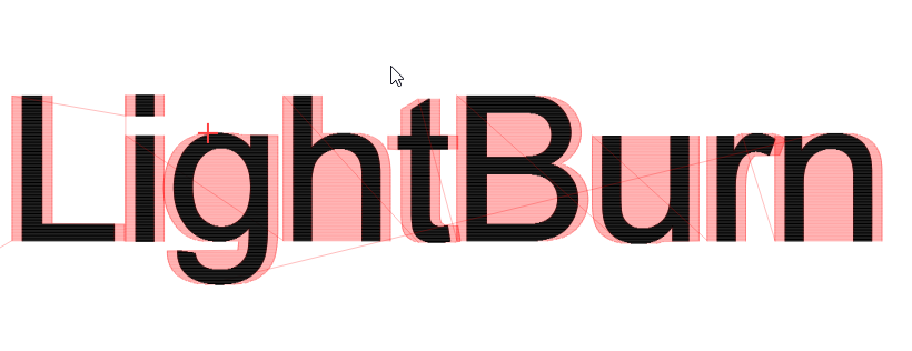
Aliasing occurs when a digital imaging system (such as a camera or a computer screen) fails to accurately represent high-frequency signals or patterns. When diagonal lines are digitized, especially at certain angles, they can produce jagged or stair-step-like artefacts due to the limited resolution of the digital representation. This phenomenon is often referred to as “jaggies” and is a form of aliasing. So, in essence, digitizing diagonal lines can indeed result in aliasing artefacts.

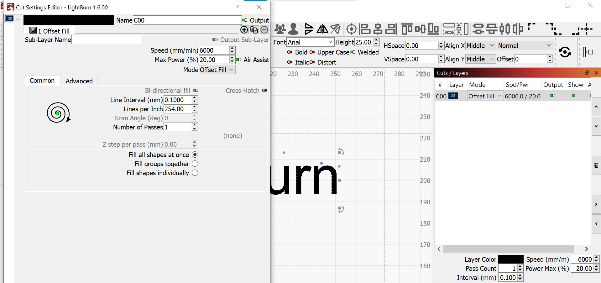
When you’re trying to represent a curve using straight lines (a process known as linear interpolation), especially in digital graphics or computer-aided design (CAD), you essentially approximate the curve by connecting a series of straight line segments. This process is often called “polygonal approximation” or “polygonal representation.”

However, because curves are smooth and continuous whereas straight lines are not, there can be discrepancies between the true curve and its polygonal representation. This can lead to aliasing artefacts, particularly if the curve is not sampled finely enough or if it’s displayed at a low resolution. So, in a way, aliasing can occur when representing curves using straight lines due to the inherent limitations of digital representation.

Your statement “Nyquist does not apply here” is actually false…

Nyquist-Shannon sampling theorem, a fundamental principle in signal processing, is indeed applicable in computer graphics, particularly in areas like texture mapping, anti-aliasing, and image resampling.

Anti-Aliasing

Anti-aliasing techniques, such as super-sampling and multi-sampling, rely on the Nyquist-Shannon theorem to smooth out jagged edges in rendered images. By sampling at a higher rate than the display resolution and then averaging the samples, these methods reduce aliasing, adhering to the principle that the sampling rate should be at least twice the highest frequency present in the signal (image).

Image Resampling

When scaling images up or down, the Nyquist-Shannon theorem informs the filtering process to avoid aliasing. Techniques like bilinear or bicubic interpolation use the theorem to determine how to sample the original image appropriately, ensuring that the resampled image maintains quality without introducing artefacts.

Practical Considerations

While the theorem provides the theoretical basis, practical implementations often deal with challenges like computational efficiency and hardware limitations. Modern graphics hardware and algorithms incorporate optimizations to balance quality and performance while adhering to the principles of the Nyquist-Shannon theorem.

The Nyquist-Shannon sampling theorem is integral to various aspects of computer graphics, ensuring high-quality visual output by guiding proper sampling techniques to avoid aliasing and other artefacts.

Regards

Mark

I said straight line, not curve using straight line, so my statement is not false.

You are manufacturing text for the sake of argument. I love mental jousting, but this is not the correct forum. The goal on this Forum is to provide information that will help others improve their laser projects. For this reason, I have nothing else to provide in this posting.

Mike

1 Like