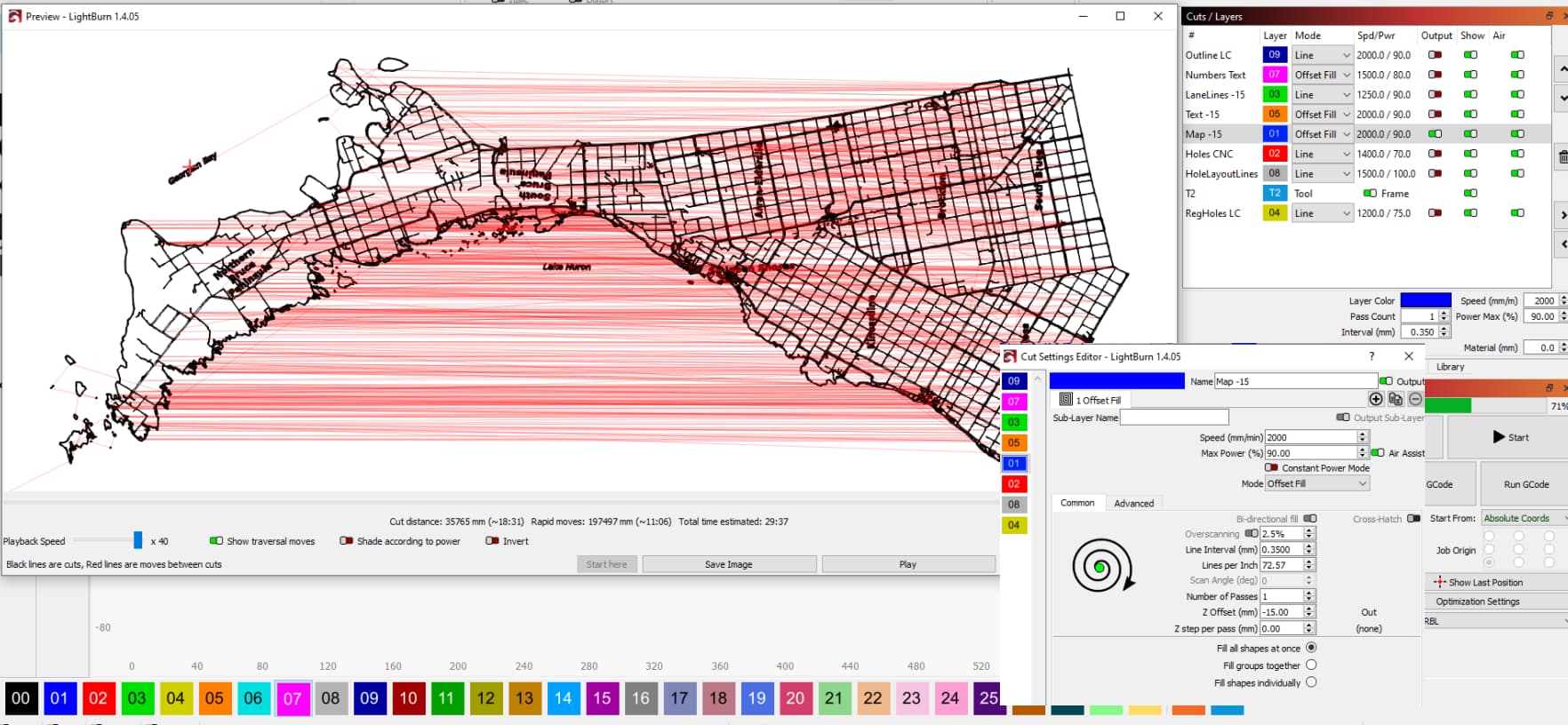
I’m hoping someone can make some suggestions on how I can optimize this Offset Fill map. I have adjusted almost every parameter I can find in Optimization Settings and in the Layer properties but it still has a crazy amount of Rapids (travel).
Go back to Fill and select FLOOD FILL from the advanced tab. Some shapes do not play well with Offset…
Thanks for the quick response. I was optimistic ant tried your suggestion. Unfortunately it was much worse.
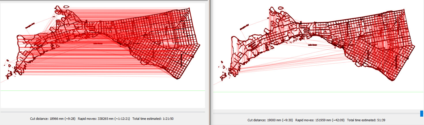
At 0 and 90 degrees, Rapid/Travel time went to 9:28/1:21:50 and 42:09/51:39 respectively.
You can also mess with the fill shapes and see which gives best results.
1 Like
What do you have for optimize settings? Some shapes are inherently bothersome for the program. You may want to cut the project in half left-right and print as two or even three separate objects.

If I were engraving something like that I would break it up over 5-6 layers.
How many of these are you doing? Is spending several hours tinkering in order to save a few minutes on the job worth it?
As an ex professional CAD designer, this was a question I asked myself regularly. Sometimes it’s worth writing scripts and building complex parametric relationships. Sometimes it’s just not.
I will go another way.
Probably you have chosen offsetfill to achieve some thickness of your lines.
If you separate the text from the lines in different layers, you can defocus your laser until the desired line wide, Power also needs to be adjusted to the changed focus.
I think Offsetfill is not designed for the type tasks like what you work with.
I have done what Bernd suggest (line mode, defocused) with nice line quality up to about .5mm wide and acceptable line quality (soft edges) up to about 1mm wide. I have never done it on something this intricate, tho. I did it to save time on a repeat job. It has widely and irregularly spaced “accent” lines across an entire nested workpiece that is otherwise all thru cut outlines. Although, having a powered Z makes it a breeze. If I had a manual Z, I’d probably do it differently.
An offset with approx. 0.2mm and a little defocusing will also do it, it takes so the dopeled time but can achieve slightly sharper edges.
“I have adjusted almost every parameter I can find in Optimization Settings and in the Layer properties but it still has a crazy amount of Rapids (travel).”
and the Rapid moves time only changes by a few seconds.
I regularly ask myself that question especially when thinking about editing the massive mesh of points in that particular map.
I’ve done about a dozen of these over the past few months and hope to do many more over time.
LB certainly does struggle with generating tool paths for large complicated shapes like this one.
When the object is rotated 90 the travel time goes from 11 minutes to 4 minutes.
So it seems LB has a left-right bias when generating tool paths that I can’t beat out of it with any cut or optimization settings. Theoretically, the object’s orientation shouldn’t affect the tool path generation.
Yep, defocusing is a is great time saver but doesn’t have much of an impact on Rapid/Travel move times.
The original image shows the cut settings where it is defocused by 15mm allowing for a Line Interval of 0.35mm.
I think I’ve lost you. If your entire road network is in line mode there shouldn’t be that much empty travel.
Which theory is this? If you rotate it 90 deg, the travel path is much shorter… The red lines are the transversal movement. If you preview them, the paths will be shorter and therefore quicker.
Sometimes it’s worth rotating the material and the graphic, then engraving in the most practical and quickest direction.
Simply put, the more time it spends over the area that need to be lased the quicker it will run. As your shots show, it’s transversing a large area with no actual work being done… it takes time to do nothing.
This is scanning…
If you are vectoring most of this applies. The least amount of distance the head has to move that it’s not lasing means a quick the job.
Good luck
Nice map… I’d like to do that for my local city… where did it originate?
![]()
If the 90 degree turn makes it run faster… Why not turn the image AND the material 90 degrees??
I am kinda simple like that.
You’re right about the regular fill process, but with an offset fill, especially for this particular object, there shouldn’t be much travel or scanning. And when it does travel, it ought to do so efficiently, moving to the next nearest island.
Thank you.
I produced that map from their public GIS site. It was a painstaking process. To get the right level of detail from the site I had to zoom it in raster sections, stitch them together, do a ton of editing/cleanup, trace the raster, and finally do a bunch of node editing/cleanup. It could still benefit from further cleanup but where do you stop?
Here’s a photo of some hot off the press. One is finished with butcher block oil, and the other is still in its raw wood state

1 Like
LOL Point taken. I’m pretty simple too but I just discovered this and there are a few other reasons why I run it with the long edge on the X axis.
a. I have heavily modded X-Carve with a router and laser mounted on it in line with the Y-axis so I don’t have as much travel on the Y axis as I do on the X.
b. It is a lot easier to keep an eye on the machine’s progress as it is lasering and milling when it is in the X landscape orientation.
c. I’m stubborn.
1 Like
I love to play cribbage. Nice product you have there, good luck ![]()