Orientation - Layout 180-degrees off from workspace - Creality Falcon 10W Setup

I could probably figure this out in the long-run, but my brain is drained after the weekend.

I design everything in the Lightroom workspace, but when I engrave, the project is turned 180-degrees (not flipped or mirrored, just rotated) on the laser.

What am I missing?

Additionally, even after watching a half-dozen YouTube videos (and they are good videos with specific details), I am still befuddled about the distinctions between “home,” “job origin,” “machine origin,” “user origin,” “start position,” and “absolute coordinates.”

Perhaps a little bit like watching the calculus professor explain things on the board which “makes sense,” but I cannot do it myself. My slowness of mind is probably annoying to those who have grasped the concepts. Apologies.

Case in point: I designed a jig for my Creality Falcon 10W engraver so that the honeycomb workspace sits consistently and squarely in the middle of the gantries.

(I also made a jig to set the rotary tool in a consistent position, too.)

I want to have the Lightburn workspace – the home, job, user, start coordinates – match the dimensions of the honeycomb workspace (ideally with a 1mm tolerance?) so that I can confidently place stock or other jigs for stock (coins, tile, leather patches, etc.) so that they are in the exact right position for engraving.

Hi Joel - I totally understand the confusion - don’t get down on yourself about it. Getting the hang of CNC work coordinates systems took me well over a year. It takes practice and some instruction, and that’s why we’re here to help.

First - we have a page that will be a bit more clear than my summary below - so please refer to here for more details: Coordinates & Origin - LightBurn Software Documentation

Workspace coordinate systems work in X, Y, and Z (for the most part) We primarily use the XY plane, aka Cartesian, coordinates.

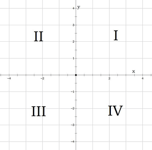
The above image shows the four quadrants of this system. Quadrant I is +/+ (x/y), quadrant II is -/+, then III is -/-, and so on. Most diode lasers ‘home’ to the lower left corner of their frame, and call this location 0,0. That point is analogous to the 0,0 point on the quadrants image above.

That means that all movements for those lasers happen in the first quadrant, all the code will be positive numbers. This is easy for machine readability! Some CNC routers work in a negative coordinates system, or quadrant III. We have a docs page specifically for those machines

Now - if you’re designing in another piece of software with an unknown coordinates system, then you bring that file into LightBurn, LightBurn has no way of knowing the coordinate system. So if your file was designed with a negative coordinate software system, then brought in to LightBurn with a positive coordinate system set up in the device settings, the geometry brought in will be upside down (rotated 180deg) - or any number of combinations depending on how that coordinate system is set up.

Next let’s talk about Work Origins

In CNC, a work origin is a XYZ location that is not the home position. For lasers, this is typically one of the corners of your material, or a special feature like a reference hole or other easy-to-locate piece of your workpiece.

image

The Start From: dropdown in LightBurn allows you to choose how you have set up your job. If you have the same location on your bed that you place your material every time, you could set up that location as either a User Origin (this is less common for diode machines, due to the lack of a physical origin button) or an Absolute Coord (an X, Y position that you know).

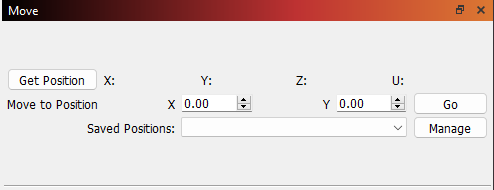
You can find the position of your laser in the Move tab in LightBurn, next to the Cuts/Layers tab by default.

image

From this part of the page you can save positions and get coordinates - say for instance you had a ‘part load’ location where the laser gantry was moved out of the way for easier access - you can do that from here.

The other option for work origins in LightBurn is ‘Current Location’ that means the laser will take the current position as home, and run from there. This works great for less repetitive jobs, simply jog to the corner of your work and press start.

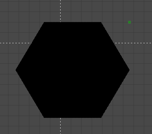
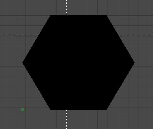
When you select ‘Current Position’ or ‘User Origin’ the green dot you see on screen is a preview of where the origin is. Your laser head should be at this point before you run the job in these modes.

image

image

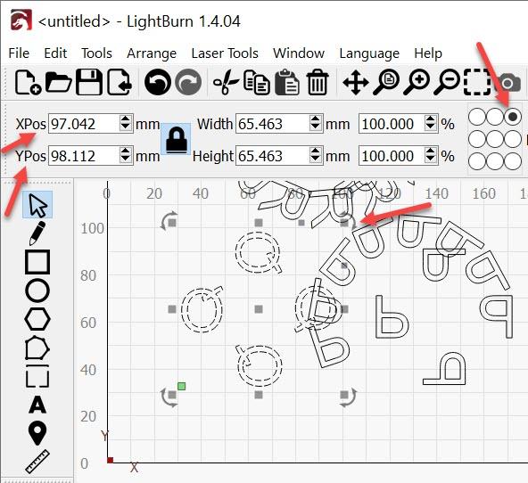
With the radio bubble filled in on the top right, the top right corner of the job is set as the start from point.

If we flip to the opposite corner, we see the green dot has moved to the lower left corner.

image

I hope that helps!

In your case, I would advise you to use absolute coordinates or User Origin and save those locations in the Move tab for your jig origins. One of the best ways to create a quick origin point is to place down some masking tape in a L shape, jog the laser to somewhere within that L, then save that location. Then, cut a rectangle outwards from that point to laser-cut a reference edge to line your material up against.

2 Likes

Thanks, Colin. While I never advanced to Calculus, I did teach middle school algebra and so your description of quadrants was one that I could grasp.

Here are a few follow-up questions which will help me make even better sense of the helpful information and documentation you shared. (You might be able to answer these questions in fewer words than I asked, but I just wanted to be as precise as possible to avoid confusion.)

  1. If I set a “Work Origin” in Lightburn, does that only affect the project that I am currently working on . . . and it gets saved when I save that project, returns when I load that project, and does not affect any other projects?

  2. If I set “absolute coordinates,” does that stay the same for ALL projects that I load until I change it? So, I could use this to find out where the bottom left corner of my honeycomb workspace is set, and when I load Lightburn and open an existing project or start a new project, the laser head will start from THAT position, and not the “Home” (0,0) position? In that sense, do the absolute coordinates in effect become the home coordinates after I have set them, until I change or reset them?

  3. If the “job origin” in the 9-point “grid” is set to the upper right, does that point in Quadrant I become (0,0), or is the (0,0) point always designated as the bottom left (Quadrant III)? (I also wondered if selecting the upper right corner as the home/origin would then affect the array tool where the toggle allows one to “reverse direction.” As in the Cartesian Coordinate system, do increased values for X always move to the right and increased values for Y always move upward – and the XPos and YPos values – up by the File Menu – correspond in that way as well?)

  4. If I want the laser head to travel to the uppermost right hand corner when the cut job is completed, do I have to edit the gcode to do that – and do I have to do that for each project, or is there a way to run that ending gcode script for every routine that is completed . . . either by finishing the print OR by pressing STOP?

  5. In the case of my Creality Falcon 10W, the workspace is set as 400 x 415. Do the grid marks in the Lightburn workspace correspond directly with the single-millimeter increments running from (0,0) to (400,415) – and correspond to the rule printed on the X / Y axes of the gantry beams?

In other words, if I positioned the Lightburn “cursor” on the Lightburn grid at (100,100), that would correspond millimeter by millimeter to (100,100) in the actual workspace of my laser?

  1. Lastly, I’ve been wondering how the “Device Settings” (wrench-screwdriver icon in Lightburn) relates to the origins / coordinates in the project settings. So, for example, if I have the upper right corner set up as the origin in the DEVICE settings, but have the lower right corner set up selected in the project’s “Job Origin” (under the laser tab menu), have I confused the system? I assume that the “Device Settings” take precedence and are more “permanent” than settings selected in each project.

I realize that this is asking a LOT of you to take the time to answer these questions (if you don’t mind), but once I have these details clear in my head, I know that I will be miles further down the road . . .

Work becomes mirrored in the direction that the origin is mismatched.

180-degree rotation of the original art is identical to flipping/rotating along both axes. The mismatch introduced between the mirrored and rotated art at 90 degrees is reversed when the second flip and the second 90 degrees of rotation are applied. I had to use a physical card to prove it to myself.

To address this, load the LightBurn file that is rotating your work. In the Laser window, use the 9 radio button selector to select the opposite corner for your Origin. Your work will now appear to be rotated 180 degrees. This is what your engraver produced - so now the settings represent the output correctly.

Now rotate the work 180 degrees, (or mirror it twice) to upright it.

Conversely, you should be able to Launch LightBurn (from version 1.3.00) without a project, confirm the Device Profile is correct for where you want to send the project, correct the origin in LightBurn, and Load the file. LightBurn should double-flip the project for you. Confirm everything is correct and save the file.

The different Start From options have different features that make both the engraver and coordinate systems behave differently. It would be challenging and perhaps not the most productive approach to attempt to match these three configurations. They’re intentionally different so they behave quite differently.

Precisely locating your work with Absolute Coordinates will rely on the precision of the limit switches during the homing operation. Some engravers do not offer great accuracy here but adjustments and enhancements can be made to the switches and the homing settings to improve this.

Precisely locating your work with User Origin relies on the accuracy of the homing operation and the accurate setting of the User Origin within that coordinate system. If the Homing operation is inaccurate and the Origin moves the User Origin will move precisely the same amount. For accuracy, confirming and setting the User Origin after each homing operation may be required. It’s not the User Origin that moves, it’s the location of the Origin during Homing that can introduce the inaccuracy.

Precisely locating your work with Current Position is entirely up to you to locate the position of the head of the laser engraver correctly. The Current Position setting ignores User Origin and the Home Position.

I am checking my work and working through the questions in your second post. Barring disaster, you should have these today as well.

1 Like

GREATLY appreciated. I knew that I was asking a lot by “asking a lot,” but even after having used Lightburn for 5+ years, the fog behind my questions has been an impediment. With your above-and-beyond the call of duty, I will get up to light-speed in Lightburn . . . and I wouldn’t be surprised if many others will benefit from your responses (and Colin’s) in the foreseeable future. Thank you!

1 Like

In LightBurn there are three Start-From options, Absolute Coordinates, Current position and User Origin.

The Work Origin is generated by offsetting 0,0 of the workspace in the machine.

I’m answering questions about Work Origin and Job Origin in terms of User Origin.

  1. a) Work origin - the work origin and where it resides is exclusive to that work. b) not sure if it’s saved or recalculated each time work is changed. c) Work Origin does not transfer coordinates to other projects. The work origins of other works are exclusive to that work. It’s possible but unlikely that they’d match.

  2. a) Yes, Absolute Coords are the same for all projects. It’s solidly linked to the 0,0 of the machine bed. The radio buttons are deactivated. b) yes, you can locate a specific point inside the work area. c) No it starts from 0,0 each time. (home and go to origin buttons are both active - double check) d) yes, 0,0 becomes home. These are set by homing switches, e) these don’t change. f) you can select other Start From options to make changes.

  3. a) The Quadrant doesn’t change unless Build-time changes are made to the axes in grbl. When an engraver operates in Quadrant III, the 0,0 is offset from the Top Right (Screen) corner toward the bottom left. Some CNC machines have 0,0 in the center of the work area. The Preferred setup is to offset 0,0 to the bottom left to make the coordinate system in Quadrant III, behave identically to Quadrant I. The Engraver is still set up for Quadrant III but It will behave as if it were in Quadrant I. b) Interesting Question - worth Testing. The Radial Array tool will start and be oriented to the workspace it’s in. Mirroring the array in one direction, by misapplying the origin would reverse the direction. Mirroring the array the second time by selecting the origin Top Right instead of Bottom Left corner would appear to rotate the array 180 degrees.
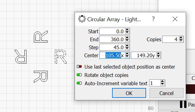
Fig. 1 Using absolute coordinates, the Origin is bottom left and the User Origin (the green dot) is bottom Left.
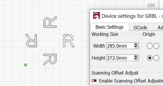
Fig. 2 Selecting User Origin, moves the User Origin up to the work according to our chosen position, but the 0,0 for the machine remains in the bottom left corner of the workspace.
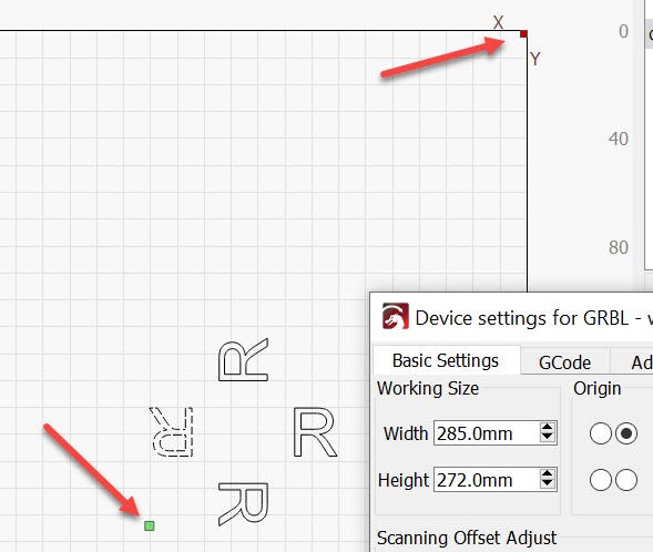
Fig. 3 Using the Device Settings to move the Origin Shows the twice mirrored array which appears to have been Rotated 180 degrees without a change in direction. (Edit - Device settings - Change Origin - click OK - then reopen Device settings)
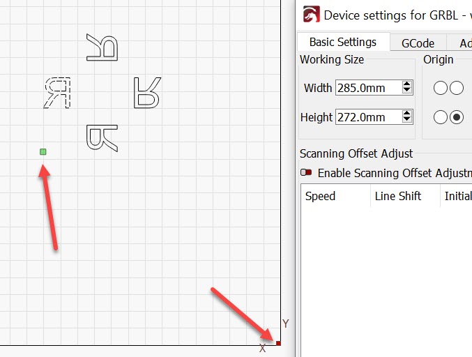
Fig. 4 Moving the Origin to the bottom right reverses the direction of the Letter and the Array.

Fig. 5 A New ‘Q’ array is oriented correctly.
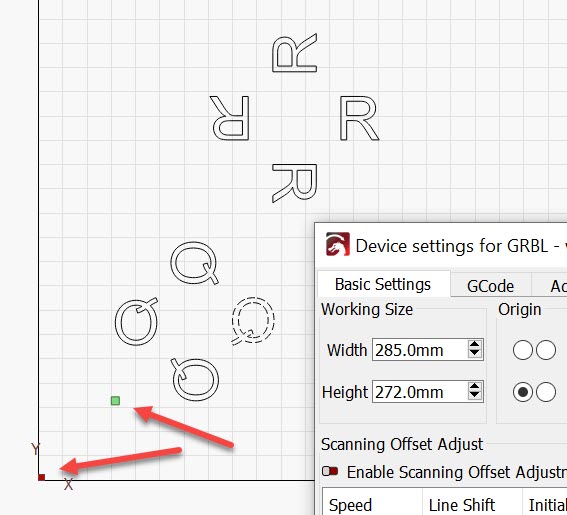
Fig. 6 returning the origin to the bottom left returns the ‘R’ array to Normal, but the ‘Q’ Array, Built in a world where the origin was bottom right Is now mirrored.
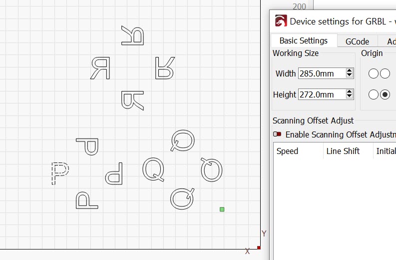
Fig. 7 The Location of the User Origin has no effect on the orientation of the new array (P).
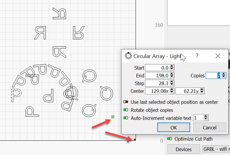
Fig.8 Here is a Partial ‘P’ array showing the progression of this new array is clockwise. User Origin and Origin are bottom right.
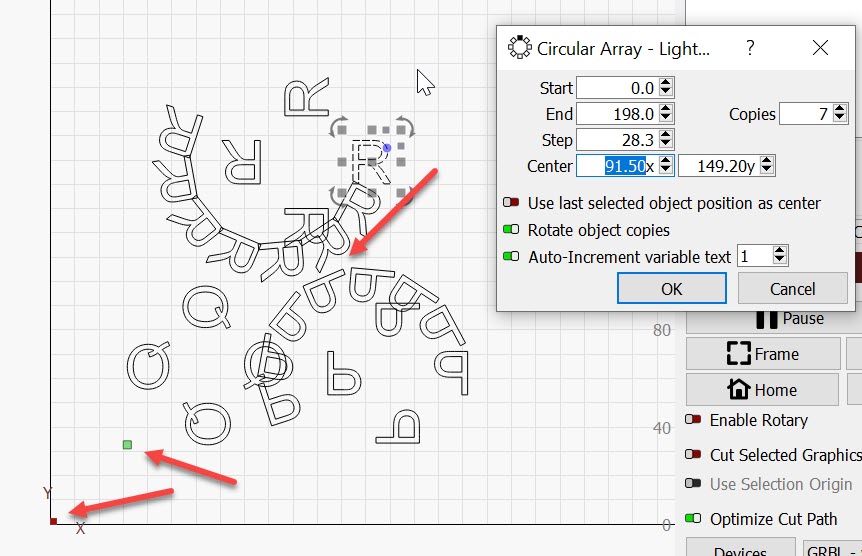
Fig. 9 A partial ‘R’ array still rotates clockwise, the previous partial Array ( P ) is mirrored and now appears to rotate counterclockwise.

  1. c) Motion in the Workspace will (nearly) always be counted away from the origin at 0,0.

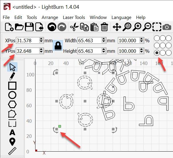
The 9 button selector on the tool bar is just a tool to refer to a point on a selected or active object.
img

Fig. 10 The Selected point is located at the bottom left corner of the selection.
img

Fig 11. The selected reference point is now top Right

Fig. 12 Moving the Origin to the top right changes the coordinate system.

This did seem to stick with the previous reference position until it updated by clicking on a button after the origin moved. Generally, For these devices, positive motion is away from the Origin. Selecting the typical Origin location in the bottom left corner of the engraver leaves us with Quadrant I (or Quadrant III with an offset applied to the entire work area). Many CNC engravers are Set up for Quadrant III.

4a) No need to edit the GCode. You can set the finish position on GCode systems. The Button is in the Move Window. b) Yes, Do this per project. c)There is GCode end script that can be added and it’s under Edit, Device Settings and the Second Tab, GCode. I believe this is scheduled to change (substantial upgrade) in the next month or two. d) I have not tested the GCode end script with the Stop button, but Yes, when the print ends the script will run.

5a) LightBurn selects the mm grid marks for me as well. The Grid marks scale with the zoom function. These correspond to the work area except for one perilous assumption. (0,0) is not in the Front Left corner of the chassis of the engraver. It is 3mm ( or the distance to pull-off of the limit switches ) away from the corner at a minimum. Even if you could repeatedly trigger the limit switch while setting the head of the engraver on the rail, you still have to release the trigger to set the origin. b) The Ruler marks on the Rail match the work area?… Almost never - especially if the ruler marks go to the corner and the laser beam simply can’t. Also, The homing operation demands that the limit switch be released in the Home state, again typically set (in Machine Settings) at 3mm back from the trigger point of the switch. 98% of the time they’re complete nonsense. I look forward to a counterexample. c) Moving to 100,100 from 0,0 would absolutely correspond to moving 100mm along each axis away from the Origin and this would be at 100,100 in the work area. If this isn’t perfect and If a dimensional error is measurable any axis can be calibrated to make it right. d) The ruler marks? Again, I look forward to the counterexample.

6a) Yes, the Origin setting in Device settings is the one that all the workspace locations are modeled from. This is why the art is mirrored or flipped when that Origin doesn’t match the Origin (usually or most often) hard-coded into the engraver. b) Fig 10,11 & 12 show how the workspace flips when the Origin in LightBurn changes corners. The Start From setting will Behave like the handle that changes corners. The engraver will Start From the chosen location and count toward or away from the Origin. This is a simplification because different motion commands can apply coordinates differently. Regardless of the simplification, the locations and motions are oriented in terms of the Origin location.
1 Like

Superb. This is Lightburn doctoral-dissertation quality: Dr. JohnJohn, LIghtburn PhD.

Much appreciated.

This topic was automatically closed 30 days after the last reply. New replies are no longer allowed.