Oval Circles (kinda) when engraving. Why?

OK so the stepped edges do not match up with the belt spacing at all. Not even close.

I have ran all kinds of materials from MDF to ply to acrylic to leather and now solid hardwood (Cherry and Walnut). The ONLY wood I have this problem on is the two types of solid hardwood.

[quote=“cggorman, post:44, topic:118804”]
The pattern reminds me of endgrain.[/quote]

I think this is part of the problem. But it only seems to happen when being cut on an arc or an angle. If I cut a square out of either the Cherry or the Walnut where the endgrain is cut perpendicular then it cuts perfect and beautiful (to the naked eye). It seems to have something to do with both x and y axes working together. Also it seems that it may be worse on some sides more than others :thinking:

Could this be a belt tension issue? Maybe one axis is too tight and struggles to keep its speed while the other axis is moving smoothly? When I move the axes by hand with the machine is off, it is stiff and I can feel every little step. But then again, I have not seen this issue on any other material. DOH!!!

Here are a couple more pics. You can see the direction of the grain and the jagged edge in one of the pics.


Any thoughts?

Shawn

Do you see the issue in only one direction or all directions?

It would seem you’ve narrowed it down to a grain issue, so maybe a change in material, orientation, speed and power will help.

I am not sure on this. As I mentioned above, it seems that it may be worse on some sides more than others. For example, if you look at the top pic in my previous post you see the stepped edge closest to the camera. If you look at the other two edges, that are perpendicular to that edge, they look pretty good with the naked eye. BUT the opposite edge (not visible in pics) to the stepped edge, it is also stepped. As you can see this piece is a square. But it was turned 45° and cut out like a diamond shape. I don’t really know what to make of this.

Changing material really isn’t an option in some cases so I will have to find other ways to improve this. I guess I will have to do more testing.

Thanks!

I also need to correct the step that occasionally occurs at the laser start/stop position. I know this is most likely a belt tension issue, as I have corrected this previously.

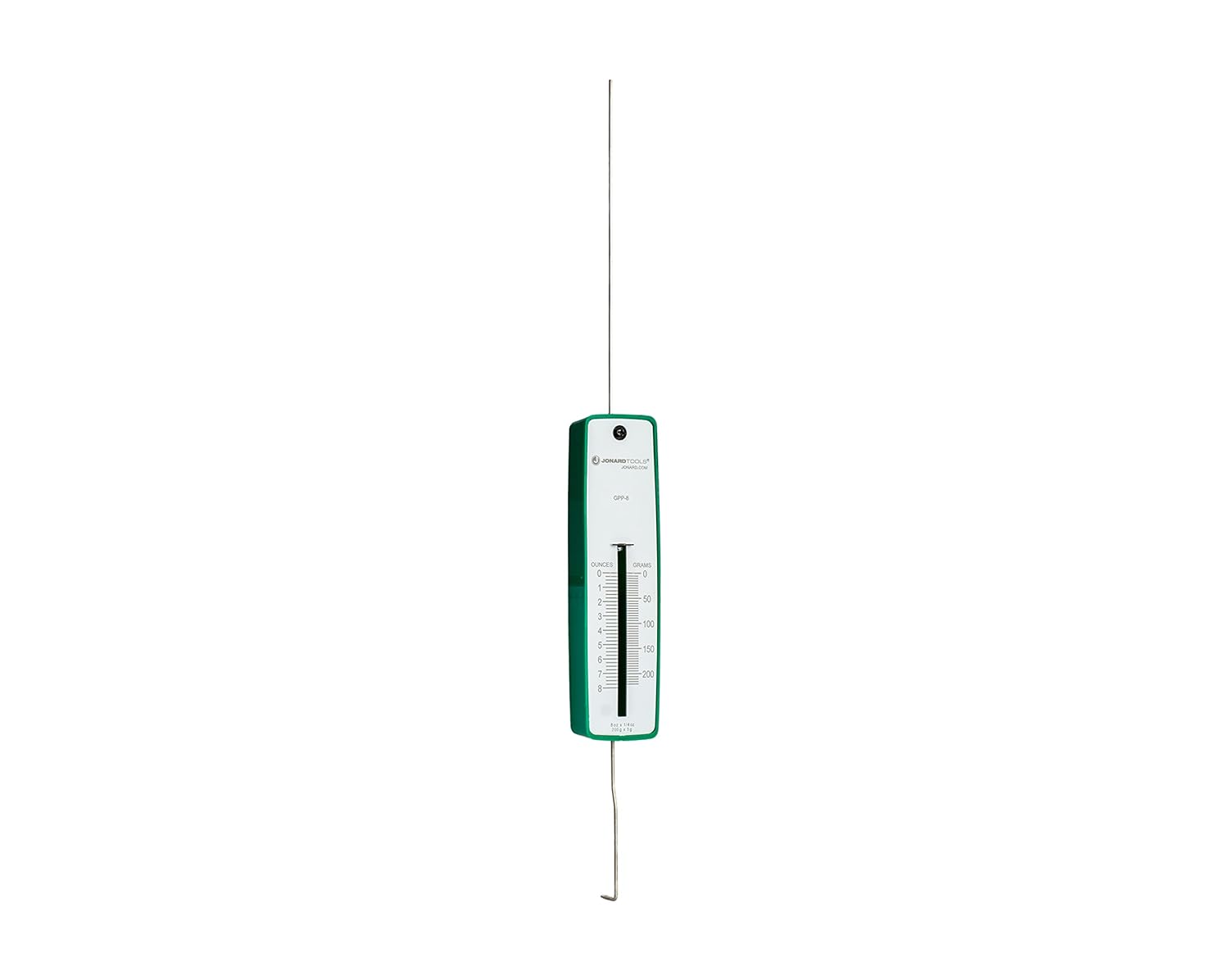
I am curious if there is a more accurate/repeatable way to setting the belt tension than guessing? I know that there are push/pull force gauges that I have seen some people mention in the CNC/Laser community. Would this be a better, more accurate way of setting belt tension? Although kind of spendy for its rare usage, I am willing to purchase one if it makes the procedure easier and more accurate. Here is one I found that.

@alanmccabe made this comment in another post.

I have often wondered how to determine which axis needs to be adjusted based on the location of the lip/step. Not sure if the pluck method is all that accurate. The longer the belt the longer the vibration will last. So I think that he may have found a procedure that works for his specific setup.

@Bonjour mentioned in the same post.

I have tried different tensions and will say that my setup seems to like a slightly tighter tension than just tight enough to not jump off the sprocket.

What is your guys procedure for setting belt tension?

I decided to run the same parts, in the same orientation using the same wood, on my 20W diode and did not notice any stepped edges. Granted the edges were slightly darker due to have to run slower but the cuts were much cleaner.

I plan to do some more testing/calibrating but if I have to I will have to run certain jobs, like this one, on the diode. Was hoping I would not have to do that though :disappointed:

After a bunch of calibrating, squaring, mirror aligning, bed leveling, belt tensioning, and testing power and speeds I thinking I am finally able to cut the hardwoods much better. After testing on some Walnut, which was the worst before, I think that the stepped edges do have to do with grain. I noticed that the Walnut has a bunch of tiny holes on the endgrain that a lot of the time run in a straight line. I think that with my power and speed settings too high before, it burned through the wood much more in those areas because of all the tiny holes, causing the stepped grooves.

If you look at this pic you can see the holes and some very fine grooves that follow the lines of holes.

Anyway, I am very pleased with where I am at now with my machine calibrations and settings.

Fingers crossed it continues to go well :crossed_fingers:

Thanks everyone for your guidance! Much appreciated!
Shawn

1 Like

Well I jumped the gun. Apparently I am still having the serrated edge issue. But now I am seeing it on some Baltic Birch plywood as well.

I have ran some tests and the slower the speed the less prominent the serrated edge is. At 15mm/s the serrated edge is pretty much non-existent, even under magnification. At 20mm/s I can start to see a tiny serration under magnification. At 25-30mm/s is when it starts to be noticeable by the naked eye.

I would normally run it at about 40 mm/s so having to run at 15-20 mm/s is doubling my machine time.

I don’t think this would be a backlash issue since both axes are running in one direction, not back and forth, while cutting a straight angled line.

It may be a belt tension issue but I feel like my belts are not too tight or too loose. I guess I will do more testing with this unless someone has any other thoughts.

In this pic notice the red arrows (serrated edges) and the blue arrows (no serrated edges) that are on the same angle. These were cut side by side but the serrations are not always in the same place as the other piece.

And if you look at the yellow arrows you will see very rounded points. I will mention that this is the back side of the pieces. The serration is more prominent on the back side than the front. In some areas there is no serration visible on the front but is on the back.

Shawn

A thought/idea came to mind just now. I recall watching a video a while back, I think it was a Russ video, that discussed and explored upgrading the air assist from the standard pump (which I have) to a compressor. I believe they discussed how the air coming out of the pump is not an even flow, but a very rapid pulsing. Where the compressor allows an even flow of air. I wonder if this could be part of the issue. It would make sense because now that I look closely at the pieces the serration is much smaller/tighter when running a slower speed :thinking:

It doesn’t explain why it is so random and does not happen on all angled edges though.

this has to be mechanical and has to be on compounding of motions
Shouldn’t be necessarily hard to replicate
Especially if you take some time to make diamond shapes but define the direction of cut

Suppose it starts up goes down on 1 diamond
But on the next by optimization of path stards DOWN and goes up

The mechanical interference you have might only happen in some directions

The fact the “serrations” are so regular in size almost 2mm per peak?
make me think is belt pitch derivated too

Edit: Start point setting tooL

I followed your advice, kinda, and cut out two of the pieces, side by side, but made all the cuts in each one go the opposite direction from the other. You can see in this pic one is CCW and the other is CW. The results seem to confirm my theory that it may be random and not repeatable.

Actually the peaks are not almost 2mm. They actually change with the speed of the cut. In this pic you can see that the 40mm/s cut is about 1.1mm peak to peak, where the 25mm/s cut is only .75mm. Yes the serrations are very regular. But nowhere near the belt pitch.

Sorry for the crappy pics

Thanks for the help!

any chance you could post the LBR of this pattern?

i just want to understand the path order
it might matter

serrated edge test - .125 BB plywood.lbrn2 (26.2 KB)

gimme a few let me look at it!

:nerd_face:

Thank you!

Ok so Bare with me

We dont need to CUT, we need to mark only

try this file in a bit of cardboard thats flat or… wood you dont mind engraving on
Must be nice and flat though so we can look at it

Your normal settings at top, rotated

Broken apart below

half speed bottom

There is some logic to my madness trust me :smiley:

Gil Test.lbrn2 (89.2 KB)

1 Like

And if possible
2nd set, to test a dif theory

Gil Test 2.lbrn2 (38.5 KB)

1 Like

Long post so if I’m suggesting something already answered I apologize.
Looking at your latest test makes me believe you still have a mechanical issue with the waviness.
I know co2 lasers have a coarser beam than the diode I use, but the corners make me think it might be out of focus.

1 Like

I will run these tomorrow morning. Thanks for taking the time!

Well after a couple of days of calibrating, aligning, squaring, etc, I ran another ramp test and have the sweet spot in the middle of my 1/8" board, which honestly the sweet spot is close to that thickness anyway. Not sure what else I can do.

I will say that these pieces are quite small and the pics are zoomed and obviously poor quality. Other than the serrated edges that I am trying to fix currently, the pieces look pretty good to the naked eye. But I am a perfectionist and I do wish the cut was better overall.

Thanks