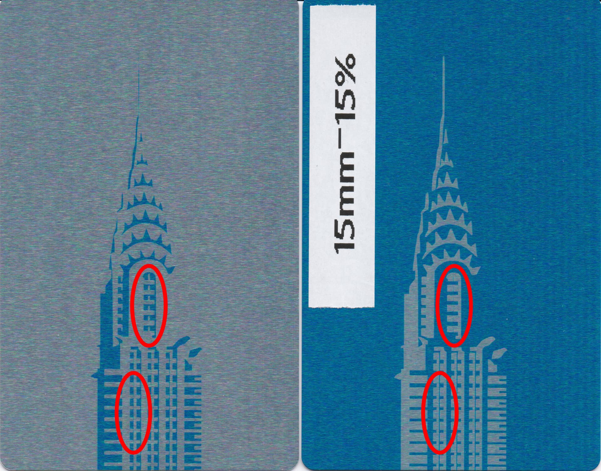
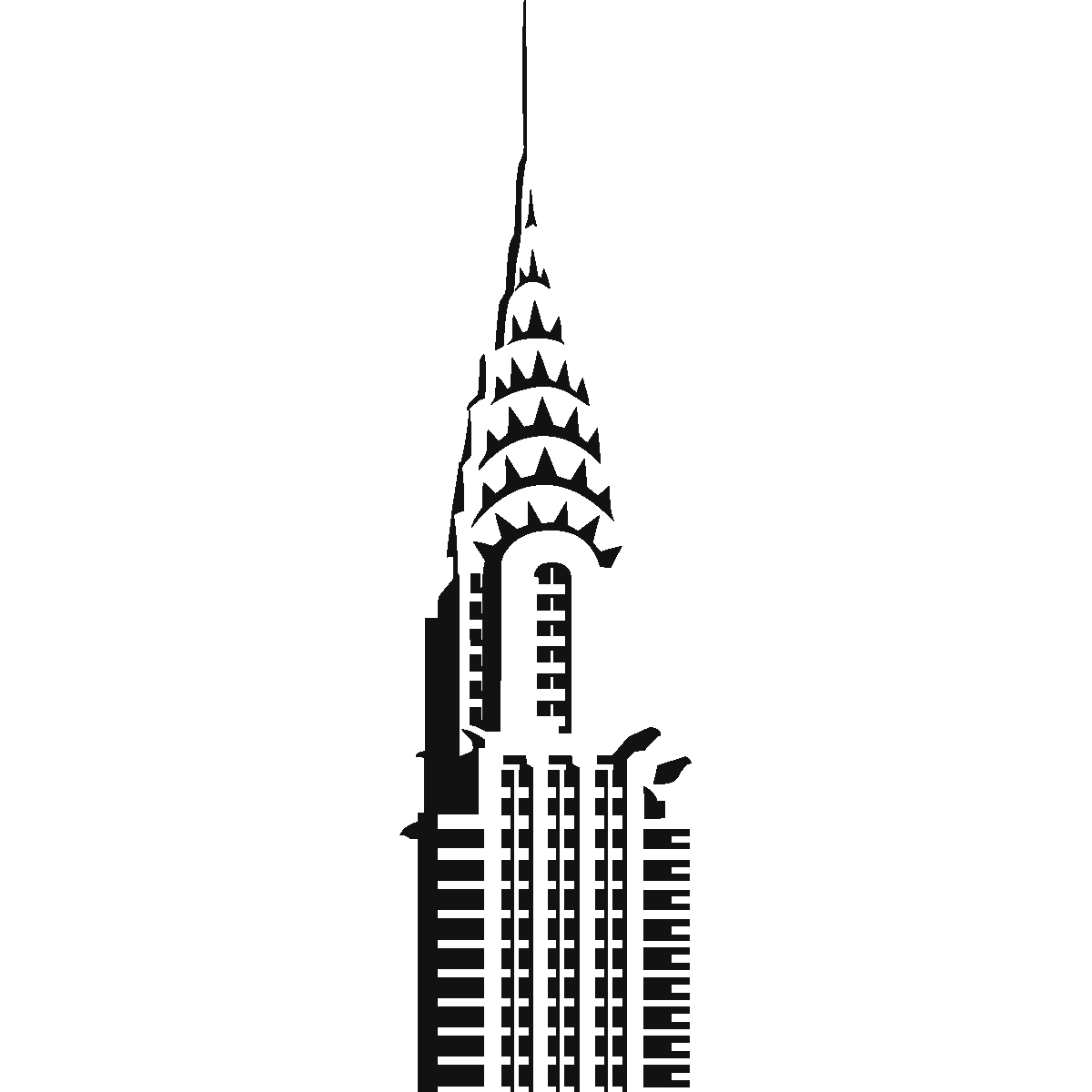
I have done a test on painted aluminum to engrave an image which I transformed into vector with the trace tool of Lightburn.
Vertical thin details are lost on engraving, which I put on the fine detail ability of my machine. Then I tried to make a negative of the same image and the details appeared, which means to me my machine is perfectly able to do these fine details, but won’t. I looks to me it keeps firing the laser a little too long.
Attached is a photo with the two engravings, the LB file I used for the positive engraving and the image I used to get the trace in LB.
Machine : diode 20W.
Settings: 15mm/s @ 15%, line interval @0.05mm (about 500 dpi), overscan 2.5%, everything else by default.
What I tried to solve this problem:
Search extensively the web and the forum (if I have missed a similar topic, I don’t know which search query to type).
doing another positive at 3mm/s @ 4%. Same details quality.
Check the Scanning Offset Adjustement: my testing accounted for a 0.006 offset, so not relevant in my opinion (3 pixels on a 600dpi scanned image).
I think part of the issue is your line interval is too low/LPI too high. What I believe is happening is you are hitting the same spot multiple times and the heat is extending past what you’re wanting to burn and eating the fine detail away. The advertised spot size of your laser is .08 and the advertised value is rarely correct. Try the area in question again with a .1 line interval and see what happens.
The other part of the equation is a little difficult for me to describe but I’ll try. The line that isn’t appearing is only .19mm wide. The laser advertised spot is .08. The laser fires centered on the line with half of it’s width going left of the line and half going right. In cutting this is called kerf but the same holds true in engraving. So you lose .04 past the end of the previous line and .04 at the start of the next section. Right there you have lost .08 of your .19 space add to that any scan offset error and the additional heat created by the large LPI and there goes your detail. These numbers only hold true if your adversized spot size corresponds with your actual spot size. It’s probably closer to .1 or .12, which decreases the visible space even more.
The reason you see it in negative is because your burning from inside out adding the .04 on each side of the .19 section. If you were able to measure the line on the negative image i speculate that it would be close to .30 wide.
I just had a thought of how to show you how the kerf size affects your narrow portion. Change to line mode, using the same speed and power as before, and run just the windows section. I think you will see a very faint line between the windows, certainly not the .19 actual size, if you see anything at all other than the burned outline. Then if you factor in any scan offset errors and added heat from high LPI you can imagine how it would not be visible.
Mate, you are right. I found out through further testing the culprit for my problem, and a workaround.
First thing: you’re right about the kerf. After my initial post, I rethought about the “dot width” parameter I read about for Lightburn, however only available for image engraving. I tested the same design of my initial post with a “offset shape” of 0.08mm inward, and I have an image closer to the original one (the sample I provided in my first post showing the negative - mostly grey - version show slightly extended gaps actually). I also tested typing some text in Lightburn with offsets of 0mm and -0.08, then comparing the width of a character leg to the theoretical one, and the offset one was correct while the normal one was too wide. I then retried two other SVGs I downloaded on the web and previously engraved at 0mm offset, day and night. That was the culprit. So the solution is to offset my paths inward with the kerf value.
Does someone know of a device setting in LB to run this inward path kerf value on every fill and offset fill jobs?
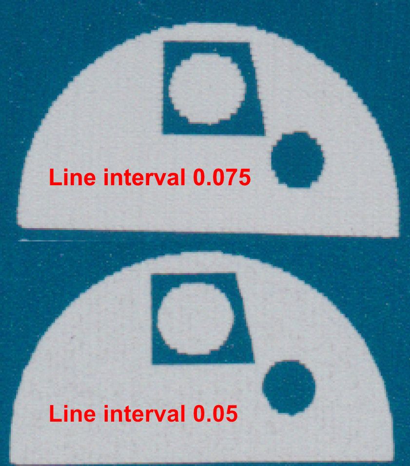
Second thing: I found the outcome of the line interval setting through testing on a previous project. Simply said, it seems to provide no improvement over these gaps, but provides improvement over the “antialiasing” effect in curved and angular shapes. See the image below.
About the gaps : I measured the total width through an imaging software, same exact width pixel to pixel for the two settings. I think I would have found some slight difference if that would have been the culprit.
About the antialiasing effect : you can already notice some improvement between the 0.05 and 0.075 versions, and let me add that the 0.1 version was even worse. The aliased result on 0.1 and 0.075 versions are visible to the naked eye, but looks almost perfect on 0.05. At least for fine detail surface like painted aluminum (I indeed think that it would not provide that of a quality gap for wood, however I shall test it).
Thanks for taking time to reply to me. I hope my experience might help other people wanting to improve the fine detail of their designs.
Just because the image is 600dpi does not mean the laser can reproduce it at 508dpi. Like @thelmuth said, burning wood at 254dpi (.1 lpi) is a much better choice.
At 0.08 dot, the best your laser can do is 318dpi (or LPI). Few diode lasers are this good.
This videos are offered a lot to those doing detailed images.
I believe this is all the result of needing to set your Scanning Offset Adjustments. The reason it appears better at the higher resolution is you are going over the same space twice, once in each direction, in effect hiding the offset.
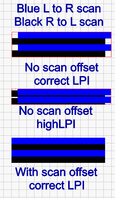
I created this graphic to demonstrate the effects of scan offset and LPI. For demonstration purpose blue is scanning left to right, black is scanning right to left. Without any scan offset and a LPI where the burns just touch each other you have the sawtooth effect. If you increase the LPI significantly like you have you are scanning the same area in both directions, masking the sawtooth effect. There may be a slight gap between scans, but it’s so small you don’t recognize it or you deem it acceptable. Scan offset adjusts your machine for this effect and the resulting image is the 3rd one with scan offset and a LPI where it just touches.
The other issue with high LPI is job time, so in my opinion it’s best to adjust your scan offset for your machine and use a LPI that just touches line to line.
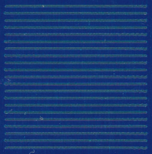
Here is a line test I did at 15mm/s. The “square” containing the lines is 10mm wide. Over a width of 236 pixels, the offset is about 1 pixel (accounting to 0.04mm).
Apart from the wobbling (which is why I now use 5-8mm/s), I see very minor scanning offset (apart from the first line which is always starting in advance). Could this still be enough to identify it as the culprit?
I also did interval tests and it gives me the same 1px difference @ 600dpi scanning (when I mean scanning, it is my printer’s scanner I’m talking about).
Those lines look very good. I don’t think I would make any adjustment at that speed. But, that is a very low speed. To get the offset dialed in you need to run tests at multiple speeds and Lightburn interpolates the values in between (I think that’s the correct word). Once you have those values set you shouldn’t need to set them again until your machine wears to the point of causing issue.
If you have issues with wobble, that’s something entirely different and not something I’m well versed in addressing.
I’m glad you ran the test. It proves that your scan offset is good at this speed. I would still advise lowering the LPI to nothing greater than 318 and i would personally go to 254 at those speeds. Something you can do to crisp up the edges is to use a line after fill sublayer. That would hide any of the antialiasing you end up with. Try it on a sample area.