Overcutting at begin/end of vectors Ruida 6445

What I’m seeing is the controller isn’t throttling back the beam enough at the start/stop points. It’s a really powerful RF CO2 here capable of 100% duty, so the Ruida is set to its max 99%/min 1% settings. The Ruida begins and ends vectors at a full stop, but not dropping the beam enough for that and the faster the vector cut will be, the more dramatic this is. It’s punching more than twice as far through acrylic as the vector should. Vectored text on plywood that is supposed to just mark the surface keeps penetrating the whole sheet at the corners.

So, this is the OPPOSITE of the dwell-with-beam-on at the start/end of vectors to give better starting cut-through. Fast tube, I’m getting too much power and too much here at the start/stop. I did try adding those delays but with 1% power trying to keep it from cutting, but that didn’t work. That’s just dead time before or after the excess burn at very slow speeds that must exist between stopped and going.

It’s not a surge from the start of firing chronologically. It seems to follow curves ok, but it may have trouble calculating the PWM as speed approaches zero.

Is it possible to see Lightburn’s output so I can see if this is a Ruida problem or within LB?

Your settings in the layer will not allow it to go below 20% power under any conditions. Probably why you are blasting stuff with that monster… You lucky dog :green_apple:

What is the controllers ‘start speed’ setting?

The start speed is where the start (min) of the power curve starts to increase. Speeds slower than this will get only minimum power.

Probably a combination of too fast a ‘start speed’ and too high minimum power on the layer. That would limit the controller into a ‘compressed’ power range.

Start speed can specified for both axes and the ‘engrave’ options.

I believe the 99% to 1% you quoted are ‘speed limits’ for the controller, that is the extent of the allowable power range. Min an Max in the executing layer are applied. Some of this is overridden when you have ‘default’ selected on the layer.

You can save the file and look at it, it’s in binary. A bunch of opcodes. No different than looking through an executable or other binary file. Not anything like a grbl file…

Here’s a shot of the rd file generated by your supplied lightburn file.

Exciting, eh?

You can check out the Wiki on the codes.

:smiley_cat:

I believe the 99% to 1% you quoted are ‘speed limits’ for the controller
No, Laser Power. Can do 100% duty and there is no threshold to get ionization and a beam, so I used the 99%/1% limits that Ruida allows. So it’s not a prob where it’s not allowed to go lower.

OK, is that something I can change? I thought “MIN” power established the duty threshold that the Ruida will put out when it’s trying to cut. I have mine set at 1% for now.

Probably a combination of too fast a ‘start speed’ and too high minimum power on the layer.

Wouldn’t this mean Start Speed is too low? That it’s transitioning to power when the speed is too slow to calculate a PWM for? Even still, with min power at 1%, it shouldn’t be able to spike through the material that far in that short period.

I’ll definitely play with this

The 99% to 1% is the maximum the controller will allow. I don’t want my tube to go over 90%, so mine is set for 90%. If I set the layers Max power to 99%, it will not go over 90%.

Change max/min power on the ‘cut/layer’

As you know the laser slows to a stop to change directions. Below your Start Speed, you get minimum, which is set to 20%, which is too much for slower speeds. Lowering the start speed allows the controller to change the PWM across more of a range, mostly at the bottom. Don’t worry about the controller and PWM it can handle all of this kind of stuff. I’m sure there are limits to everything, but I doubt you are there with this issue.

The controller looks at Minimum and Maximum power set on your layer. This combined with the Start speed, it computes how much power at a certain speed.

If the Start Speed is 20mm/s and minimum is 20%, anything below 20mm/s gets low power. Lower Start Speed allows the controller to change power at those lower speeds. This is what’s restricting your low speed power control, along with the minimum setting on the layer :slight_smile:

I’m thinking a minimum power of 1% and a minimum Start Speed of the 1mm/s to see how it works. Never had the pleasure of a laser like yours so these are just guesses. Can’t think it would hurt anything.

I’m trying to lower the power of your laser as you slow down to a stop. Most of us can’t ‘lase’ at these low levels (read that as ‘green’) so you can move the bottom or the minimum power to occur at a slower speed.

The ‘Start Speed’ is in the ‘Edit → Machine Settings’

Does this make any more sense?

:smiley_cat:

Actually I’m still confused.

If the cut is declared at 99% power 50mm/sec, and the tube is 99%/1%, then I figured the controller is going to start at 0 mm/sec and proportionately increase power with speed as it accelerates until it’s at then specified PWM at the specified speed. 10% power at 5mm/sec, 20% 10mm/sec, 50% 25 mm/sec. Some tightly figured curves may never reach full speed and thus never reach full power but that’s ok.

This is what I don’t understand yet- wouldn’t “start speed” go the other way, and just not provide any power if the speed is below the start speed? If larger numbers mean “anything below this gets the min power % PWM”, that’s the opposite of my prob. 1% laser PWM at 0 or 1mm/sec speed probably wouldn’t cause this. If the start speed number is large, then it’s going to revert to 1% at say 10mm/sec and the ends/corners of vectors would be shallow where it had to slow below 10mm/sec. Not overpowered.

But I will certainly tinker and see.

At 1% PWM, the laser does have ~1% output, although it’s unlikely to actually create a cut in most materials, so I’m not sure if that’s the best value.

The 1% to 99% tells the controller any value you have sent to it within this range is ok to execute. That’s it. Has nothing to do with what the Ruida is computing for power. It’s just a limit it can’t exceed.

If you tell your controller to go 20000mm/s will it? The controller has an internal speed limit to prevent it from being over driven by the software.

I can set my layer speed to 20000mm/s, but the Max Speed will limit the machine to 1650mm/s.

Screenshot from 2021-11-09 14-06-38

Your minimum and maximum power settings from the ‘layer’ are used. If it’s set to a max of 60% and a minimum of 40% that’s the complete range of power, no more or less. Anything below the ‘start speed’ get 40% power. Above that the power is scaled going to 60% maximum over the speed range.

What you’re missing is where you tell the controller at what speed it is to start controlling the power. The ‘start speed’ and the minimum in your layer is where the controller starts varying power.

What if the material you are doing does not respond to anything less than 20% power but you are cutting at 10mm/s. If the controller went to zero, you part would be wasted. So you need to be able to control where the power curve starts.

What is your ‘Start Speed’ set to?

Hope I’m not confusing you more…:frowning:

:smiley_cat:

I understand most of that.

Start Speed was set at 1%. Min power at 1%.

So if it’s below the Start Speed, do we get NO modulation to the tube, or the Minimum? Because at a standstill, then 1% may still be too much.

I’ve been tinkering with it, not sure what changed, but I was tweaking freq and speeds- I didn’t see the dramatic, thin spike at start/stop, but it’s definitely overcutting around start/stop points, by about 50%.

You will always get at least ‘minimum’ from the controller. I don’t go below about 9.4%, my tube won’t lase. If I set it below where it lases, it will not fire on some parts of the vector. The PWM is there, but the tube can’t lase at such a low PWM rate.

You can set Minimum on the layer to 0. So the bottom is 0 and 1% of zero is…

You are going to have to face the fact that there are limits, you may have too much power to do delicate work. I don’t know if there is a 0.1% option on the controller. I know it won’t take zero, but the lowest is the lowest. If that’s too much power, I don’t know what to say except you have too much power to the do the job you wish.

It could be that you are trying to drive a tack with a pile driver.

Some things get a little crispy because I can’t lower the power enough on corners with a vector cut, such is life.

I wanted a more powerful laser when I got mine. What I have found is that the 50 watt machine does very well with the stuff I engrave at 10% power, that’s about 4.5 watts (45 watt tube in reality.) A 100 watt tube at 10% is 10 watts, twice as much power as I want and will ruin the work. So I will probably only go to a real 50 watt or 60 watt at the largest, when this one expires.

Keep in mind that your laser, my laser do not really have power control. PWM is an illusion as it’s only valid ‘over time’. You PWM signal turns the laser on when it’s high and turns it off when it’s low. So in reality, when it’s lasing it’s lasing at 100%. There is no third ‘state’ for a ‘50%’ setting. That boils down to the only real control you have is speed when it comes to lasing.

Before you get too excited, what have you changed?

Did you change the layer minimum and maximum?

I’d stay away from frequency until you get a better handle on how this is working.

I hope you backed up your configuration from the Ruida.

:smiley_cat:

I disagree. The laser has no prob operating consistently at very low power, this is a control system hitch. That doesn’t mean I’m certain LB/Ruida has an answer right now for it, but I’m certain this is not a physical prob with the system.

I did switch to dashed-line mode with speed set to go halfway through the acrylic. The dashes do not begin and end with any overburn. It’s just not compensating correctly at the start/stop. I’m thinking this is a straight-up bug in PWM calc that has gone unnoticed because machines of more conventional power don’t launch into start/stop points so fast, or even respond to low PWM duties like this. Is the PWM period-vs-actual-speed calculated in the Ruida, or LB?

I aligned by firing the laser at 0.3% with a “mood ring” thermochromic sheet and can see the beam live. It was pretty awesomely helpful.

The Max/Min power is 99% and 1% on Ruida. It will pretend to take 100% and 0% but then change them and you won’t see its correction until you exit and return to the menu.

I’d really like to see more about what it’s doing, like put a scope on the PWM output, but without correlating to head movement that’s of limited value.

It absolutely is a problem that could in theory go away with better system control. I don’t think the laser is actually running with any nonlinearities, just that the final dynamic PWM level is a bit wonky. There’s no correction chart for power levels, right? I didn’t see one.

I got it to do an excellent cut through 1/2" black acrylic with a 2" lens at 8mm/sec, so I’m quite happy having a machine that probably violates a strategic arms limitations treaty.

You may be right, to some extent, wish I had such a toy…

Let’s make sure of what you changed…

These three?

And changed the min/max on the layer?

To what values, out of curiosity… :slight_smile:

The hardware in the Ruida figures it out. LB reads the configuration data off the Ruida to estimate the time required to execute on the machine.

Yea, there are a number of places you can enter a value, but when read back, it was never changed. I would assume that it’s the Ruida, since the console works the same way. Since LB confirms it was written, I have to assume LB can’t tell if it failed…? They are on top of everything else.

:heart:

My guess, is that the hardware is performing correctly. These are all over the place running RF lasers, so I’m sure they been pretty well beat up.

On my machine, I hang a scope off the PWM and watch the voltage across the ma meter to give me some idea of how the power supply is responding. I’m installing a 30kv meter to keep an eye on the HV. That might give me a better clue as to it’s operation.

Is there any way to tell how fast your laser is responding to the ON signal?

Is there any specification on how fast your laser is supposed to respond?

The other night, it dawned on me that I do know someone that has had dealing with a rf co2. Russ Sadler, ever hear of him?

If we don’t figure this out pretty soon, I’m pretty much out of answers and he would be a good person to contact. But I’d like to ensure we’ve covered all the bases.

:smiley_cat:

Hmm, I didn’t think to look for individual X start and Y start. They’re probably still set to something!

But this is still in the wrong direction, right? The Starts just delay the beam until the axis is moving, so a value being in that box could resolve this problem, rather than create it.

It’s kind of both a crazy thin, deep spike of overpower at the endpoints (seems to have gone away with settings changes) and a “wing” of excess power in the starting and ending 6mm or so that is about 60% more that it does at constant-speed.

I did bump the PWM freq down to 5KHz, which should be fine. It doesn’t seem different than 10KHz or 20KHz.

If you modified the remaining one, it probably did nothing since you are not ‘engraving’ (scanning).

The start speed is where the power starts to increase with a speed increase.

I would think you would want this to be as low as possible.

It will ALWAYS be at the layer ‘minimum’ power until this speed is reached.

Once that speed is attained, the controller will start applying the power curve to the PWM.

:smiley_cat:

It will ALWAYS be at the layer ‘minimum’ power until this speed is exceeded.

But only during a cut, right? Not while rapid or idle dwell at the start of a cut, right?

This doesn’t sound like a useful thing for me. I did play with the number but it doesn’t appear useful- if this number is significant and someone specifies a very low feedrate and low % beam for some sort of effect, the machine may not respond if the beam is too slow.

Can the power curve be adjusted? Sounds like not, I’m seeing that the LB passes a 100mm vector to be cut at 50mm/sec at 99% power/1% min. As it accelerates, the Ruida is just proportionally reducing the PWM duty to the beam based on % of target feedrate. So where it the head has accelerated to 10mm/sec, the PWM would be trimmed at 20% power. But it doesn’t appear to be doing this.

Exactly right and it burns people all the time.

That’s why I was saying my min is 9.4%. If I set it for below that, when the head slows the laser can’t fire. So it is very useful, for us that are not as lucky as you…

The min, max values determine the power range. ‘Start Speed’ in the controller and Speed (mm/s) in the cut layer determine the speed range. That’s all the controller has for information.

Is this what your cut/layer is set to?

:smiley_cat:

Well, I put the PWM on a digital oscilloscope. It’s got no obvious defect. Starts with a very thin line and progresses to greater duty cycles, and tapers back to 0 at the stop.

It’s just that its concept of proportioning isn’t adjustable, and it looks like it has added nonlinearities built in to work accurately with some other hardware.

I did test for laser hardware issues by using the “dash line” function. Net result- overburn slope at start and end of the whole vector only. The laser pulsing on and off once it’s at constant velocity is perfectly even. It’s that the motion-controller-calculated proportional duty reduction for non-CV acceleration regions is off.

IMHO, even if you knew the head speed, you don’t know what the Ruida is programmed to do. If it’s a straight line power/speed ‘curve’.

I’ve only seen a couple of ‘curves’, at least one here on the min/max control, can’t locate it. I don’t think any of them were a straight line.

I think you’ve pretty much exceeded what I can do for you. Plus no way to ‘go try it’ like you can.

Maybe one of the wizards will chime in on this, maybe @LightBurn can help.

Good luck…

:smiley_cat:

On DSP controllers, If you are running a cut at very low speed, set your Min Power and Max Power values to match.

There is a setting in the Machine Settings, called ‘Start Speed’, that specifies the value where the controller begins ramping the power from Min to Max power. If the laser is moving at this speed or slower, only Min Power is used. This setting is 10mm/sec by default on Ruida controllers, but some machines may have it set as high as 15 to 20 mm/sec, or may have it set lower. Output issues - LightBurn Software Documentation

Search from this forum for ‘Start Speed’: Search results for 'start speed' - LightBurn Software Forum

I think we’ve been thought what I read… His issue is his RF laser can lase at 1% and he wants it to be off at 0 speed. Doesn’t feel the controller is handling the power curve properly. Burning edges on vectors.

He advises that he’s set the Min/Max for the laser tube to 1 and 99 and his layers to the proper Min/Max along with a lowered Start Speed.

Thanks…

:smiley_cat:

Yep, Jack gets it. “start speed” and “min power” are dead ends.

The basic expectation would be that a controller, in dynamic accel not constant velocity (start, stop, hitting corners) would throttle the laser proportionately based on ratio of instantaneous velocity over target velocity. e.g. 100mm/s 100% max power/1min power, when it’s accelerating and only at 20mm/s actual, the laser would be at 20% of max. If you gave 80 max and 20% min power, you’d get 32%, since that’s 20% of the scale.

But, it appears not. They weighted it in a nonlinear way, boosting the lower % range, for… reasons, like monitor gamma. And there’s no way to override or adjust it to something else. PWM freq won’t change anything, it’s the duty they’re coming up with.

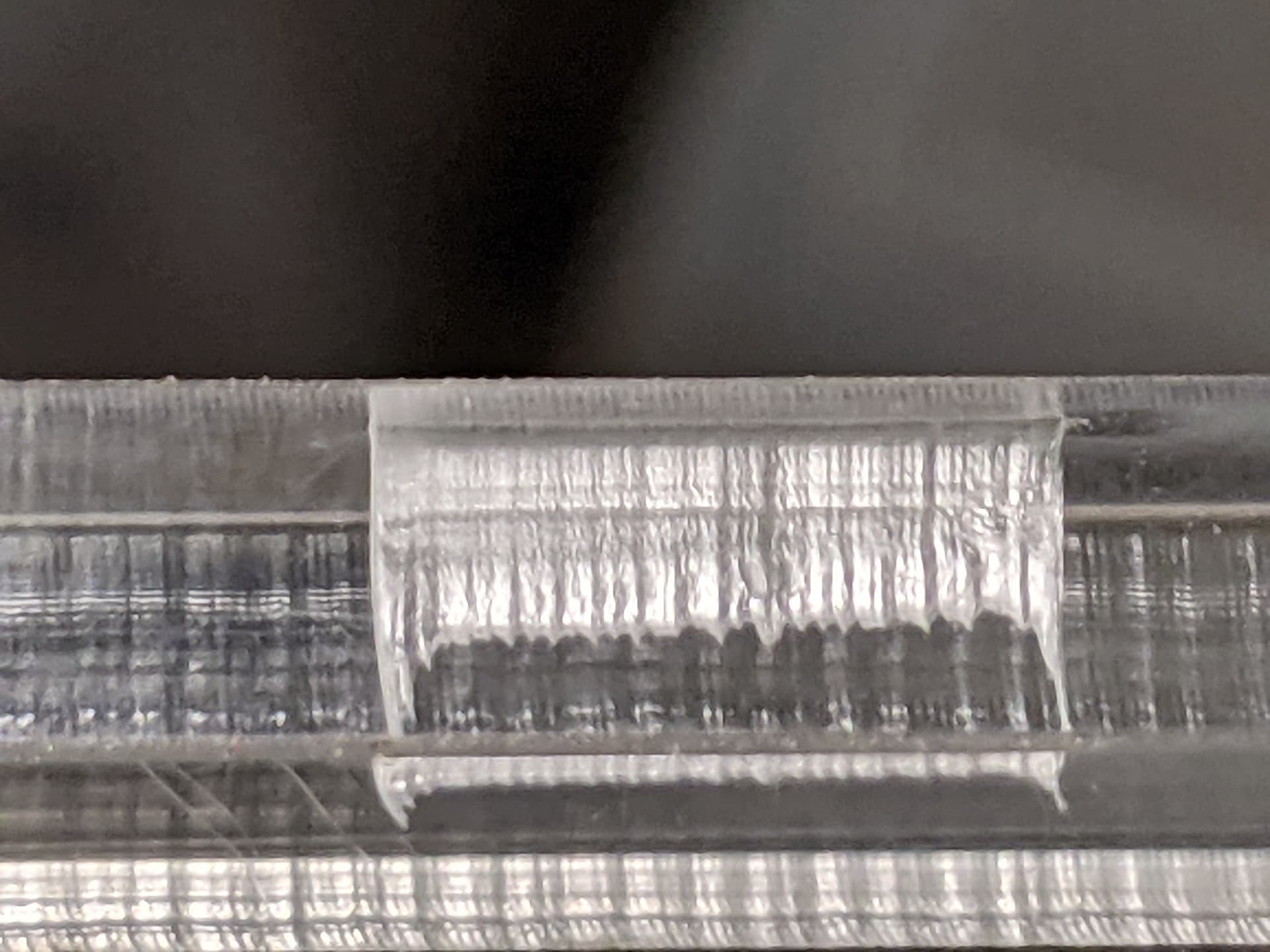
Can you achieve a cut through? Yeah, this nonlinearity won’t even matter, actually, for cut through. It just overpowers these spots. It does not weaken the constant velocity portions.

It’s in vector engraving, it’s inconsistently applying overpower in curves. This is clearly apparent on acrylics. I’ve accidentally punched all the way through plywood on vector text corners.

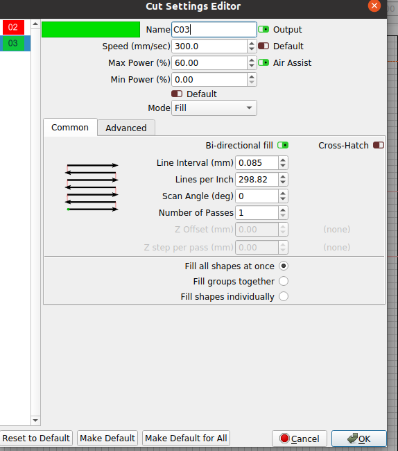
“min power” is 1%, setting anything higher would the wrong way for dynamic acceleration adjustment. It would push the power higher on the proportional side, not lower.

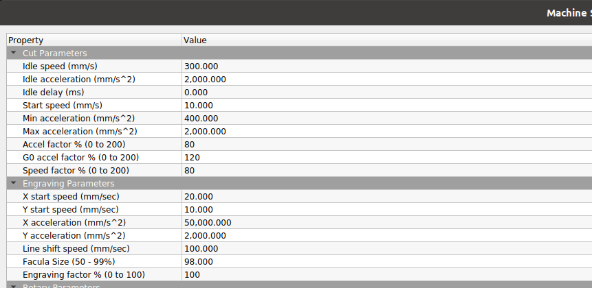
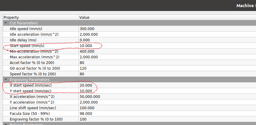
“Start Speed” just clips the power until a certain speed. That could prevent something from being cut, but once it starts, the overpower is still right there.

e.g. as per prior example, 100mm/s target speed and instantaneous velocity is currently 20mm/s, I’m apparently getting more than 20% PWM. We could say “start speed= 15mm/s”, well, then there’s no vector cut before this. From there, I’m unclear if 20mm/s is going to be the same calc, or it offets the calc over and instead of being 20% of target v it calcs like 5 of 85 of the target? That actually could be better sort of, but still nonlinear and creating a major new nonlinearity.

We never used it, but at least one of our Universal Lasers had a power correction table for interpolation. As best I understood it, it has entries for each 10% interval, and this is how much to reduce the beam from target power when below target velocity. By default, 10% of target speed is 10% duty of target PWM duty and we never changed from that and get consistent depth of partial-thickness vectors in acrylic across start/stop/corners. Maybe a teeny tiny underpower bit at the start because it doesn’t have a start dwell to preheat the first 0.05mm.

It looks like Ruida has such a correction chart, but it’s hardcoded, and hardcoded to something nonlinear.

1 Like

This topic was automatically closed 30 days after the last reply. New replies are no longer allowed.