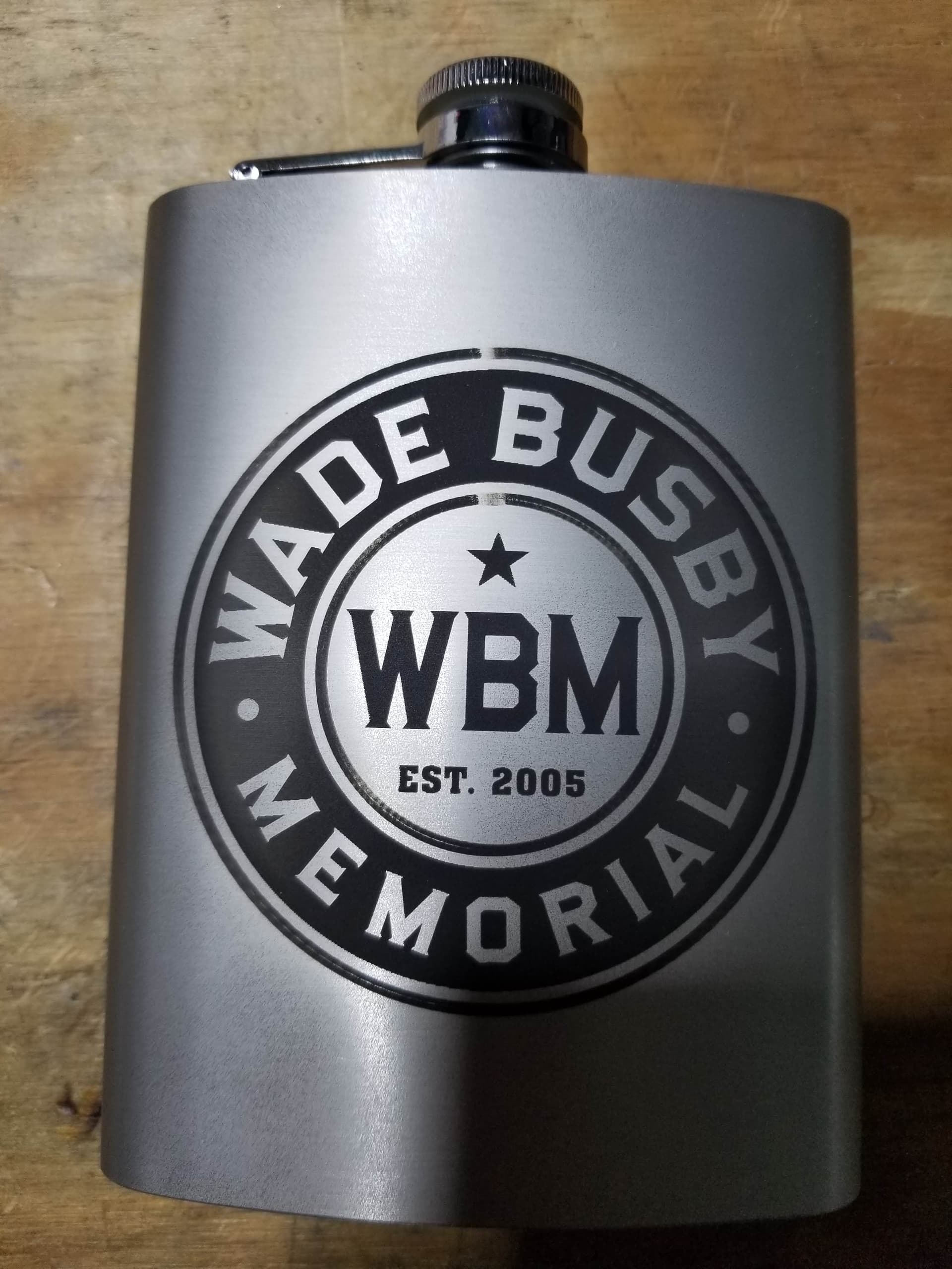
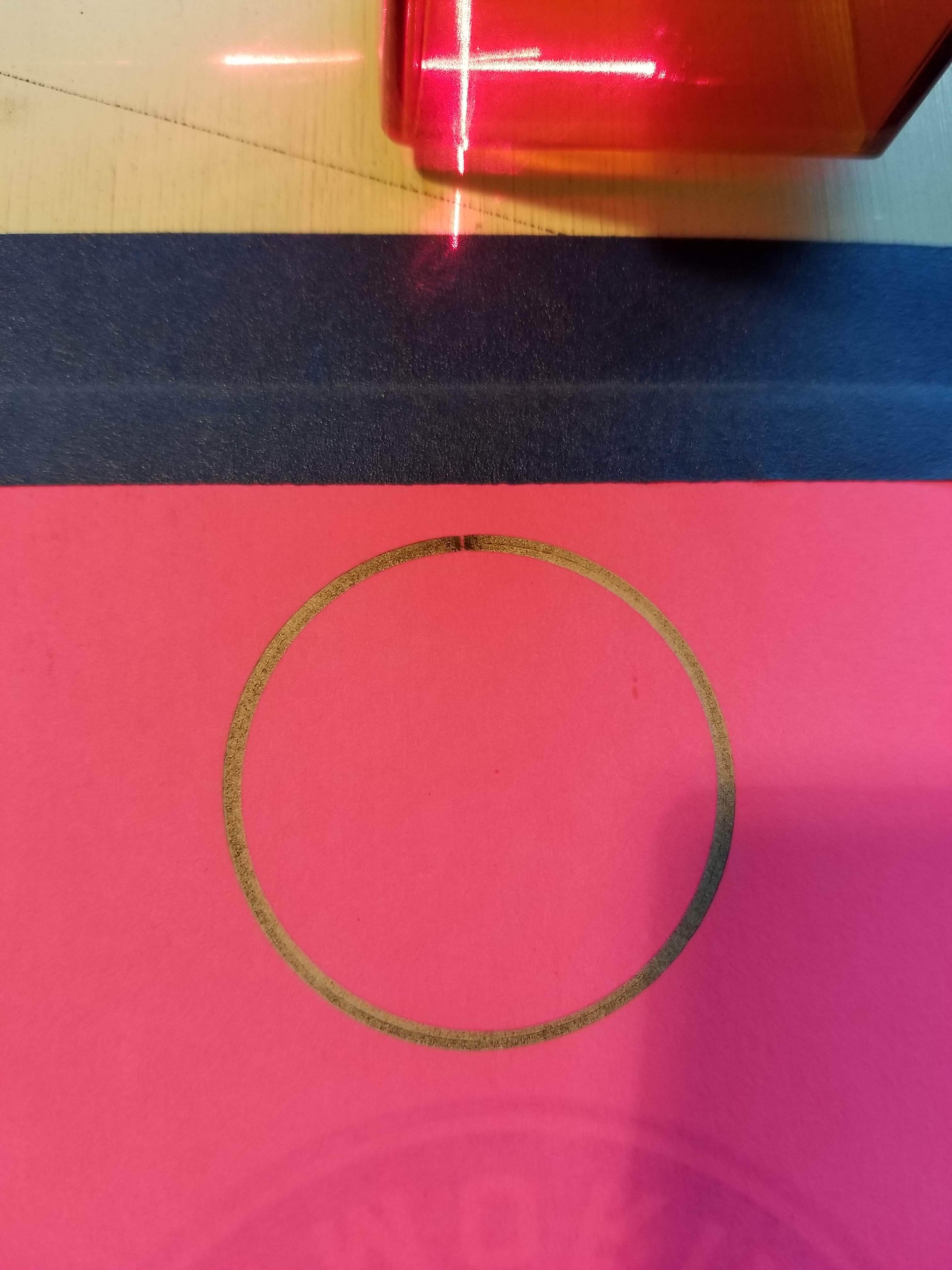
I recently ran two projects. One was slate coasters, the other stainless hip flasks. Other than power and speed all the settings were the same (I’m pretty sure). They both contain circles that are to be offset filled. The coasters came out fine. The flask not so much. I could see the laser turn off for the segments of the circle that did not engrave. Any idea why it would do this? Also, the circles didn’t really engrave all that well; more LPI? It was set to 254 LPI. The faint engraving you see in the skipped segment was my feeble attempt to “patch” it after the fact. Epic fail.
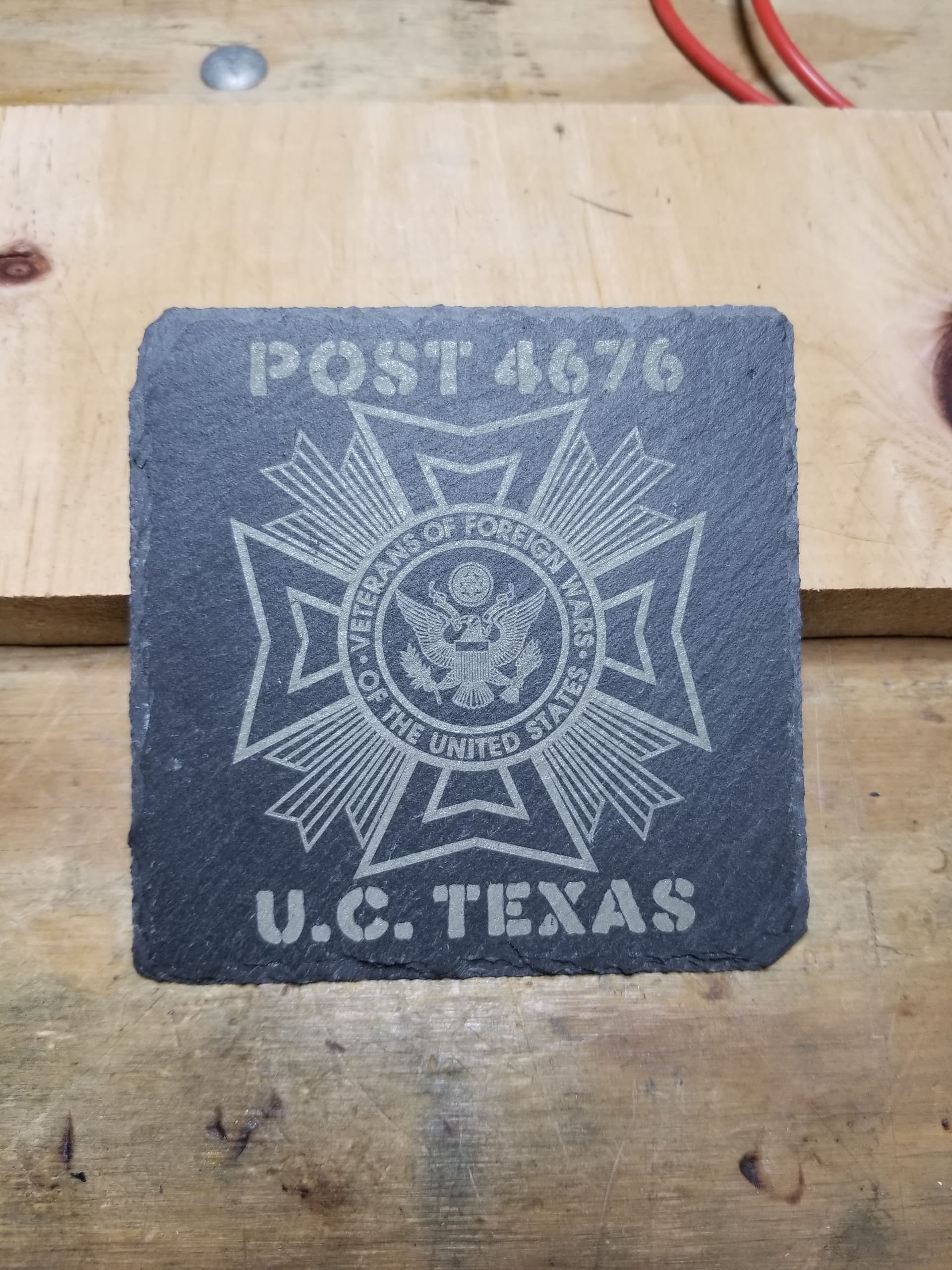
I’ve done a lot of slate, along with a lot of coasters in slate. I think 254dpi with that material is about the best you will get. I have a co2 machine and I use 254dpi, but it’s a maximum. If you look at the slate with a microscope you can see what kind of damage you can do and if it the damage is small enough for that high of a dpi.
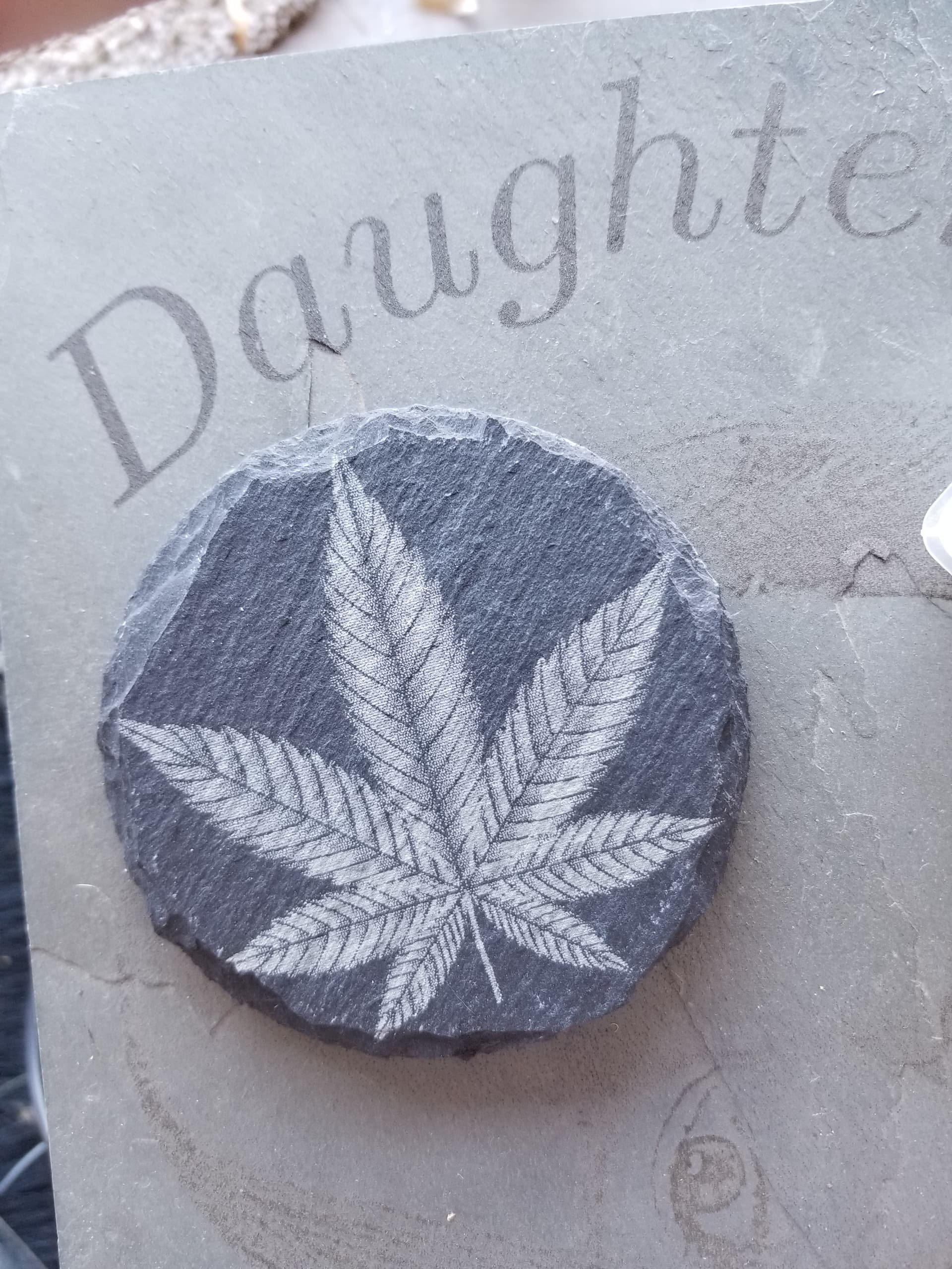
It also changes between batches and types. I did some coaster for a friends cbd business…
Notice that one type lases white the other dark…
What type of coating are you using for the flask? I’ve see something similar using TiO2 and Laser Bond 100 spray. Variations in the coating thickness are usually visible. A thicker coat will reduce the resolution and require higher power since there is more there to melt.
Both of the circles have poor fill in many places. Can you use the offset to add another circle and just use fill?
![]()
I ran out of TiO2 (Enduramark) which didn’t coat evenly anyway. I did these flasks with Chalkboard spray paint (Rustoleum) which sprays very nicely and coats consistently. The reason I went with offset fill is that it cut the run time down significantly and seemed to work fine with slate.
I tried the rustoleum game, had the same problem. Looked good, but chip it off and it’s different thickness.
Ended up buying TiO2 in a bag from amazon and mixing it with water. Use the air brush. None of them seem very consistent for a minimum layer thickness. Some recommend alcohol with the TiO2, but it seemed to just ‘run through’ the air brush and leave a lump of TiO2. Tried using both ethanol and methanol.
Does this just happen with offset fill? Do you get a flat side…?
![]()
It wasn’t a problem with the coating. I could actually see the laser turn off when passing those two missing spots.
Might be something you should ship to support and see if there some kind of problem with the algorithm.
![]()
Is it possible that the change in elevation across the flask pushed the focus out of whack enough to make the light appear to go out against the black paint?
I would set the focal height to a block of wood at the median height (half-way between highest and lowest height) of that flask.
The coasters prove that the program is good and that the majority of the bottle proves that the settings are good.
The missing spot on the flask is at the highest elevation in the art so my thought is focal distance.
1 Like
I don’t buy it. Wouldn’t that leave a gap down the middle of the whole thing? It was only those two spots… exactly the same on two flasks.
Check the Preview for the flask and make sure that the areas where you saw a burn gap are indeed filled in on the Preview.
If so, I suspect this would be a firmware issue for the xTool D1.
Are you on the latest firmware?
Are you able to reproduce the issue while just burning one of the concentric circles? If so, save the gcode for just that portion and I’ll review it to confirm.
Or else upload the .lbrn file and I’ll review.
Preview looks okay. Firmware was updated recently to accommodate the RA2 Pro rotary attachment.
I reproduced it on flat cardstock - both the entire burn and just the inner circle.
It won’t let me upload a gc file or a zip file. How am I supposed to get it to you?
Change the file extension to .txt and the forum will allow you to upload.
circle-test.txt (33.3 KB)
I don’t see anything in the gcode that would cause the laser to turn off at the top like that. So again, suspect something in firmware. I see that the path looks like it goes in one direction for half of the fill and then reverses direction for the other half. This is a little odd but shouldn’t cause what you’re seeing. If the direction changed every time it reached the top of the circle then I could see this contributing.
One thing I’m curious about, though. Are you using Constant Power Mode for this burn? I noticed that the M3 command was being used rather than M4. If so, any particular reason for this? And if so, you may want to try not using Constant Power Mode as it’s possible that there’s a firmware issue specific to that command.
I thought it was a bit odd, too, switching directions like that.
Yes, I use constant power mode all the time because why not. I haven’t done anything with grayscale so why wouldn’t I? Maybe I don’t understand what it really means…
BTW, I’m new to laser engraving and Lightburn.
I’ve got a couple items to get out the door; then maybe I’ll have time to explore this further.
Constant power mode is actually a downgrade in terms of sophistication. Enabling constant power mode effectively disables laser mode and variable power. Specifically, the ability for GRBL to modulate power to accommodate speed changes from acceleration/deceleration. This reduces burn at corners where the laser will need to decelerate to turn. Also reduces burn at the edges of a scanning operation.
This is different than the power changes associated with grayscale images.
Generally you wouldn’t want to use Constant Power Mode unless there’s a specific artifact that you’re trying to address. What’s odd in this case, though, is that Constant Power Mode is actually allowing power to be cut.
Offset Fill is using vector lines, and if you’re not using “Constant Power”, the laser will ramp up / down in power as the speed ramps up / down at the start and end of vector lines. It’s a caveat of using the Offset Fill feature.
Constant Power mode might help, but then you’ll be a little over-powered at the start/end points instead of underpowered. When using a marking spray on steel this is probably fine, but it’ll look funny on wood.
A better option for your design would just be to use normal “Fill” mode, and enable the Fast Whitespace option.
1 Like
Most of the machines I use will allow you to add another extension.
I try renaming, retaining the original format. If it’s a “test.gc”, I’ll rename it “test.gc.txt”. Gives a clue to the reader of it’s original format.
The site doesn’t seem to have a problem with this format.
Is circle-test.txt a zip or gc file?
![]()
It’s a gc file.
I have always used constant power mode without really knowing for sure why. Just made sense with single color graphics.
This topic was automatically closed 30 days after the last reply. New replies are no longer allowed.