PCB etching on a MOPA after Drilling/Milling with MillMage

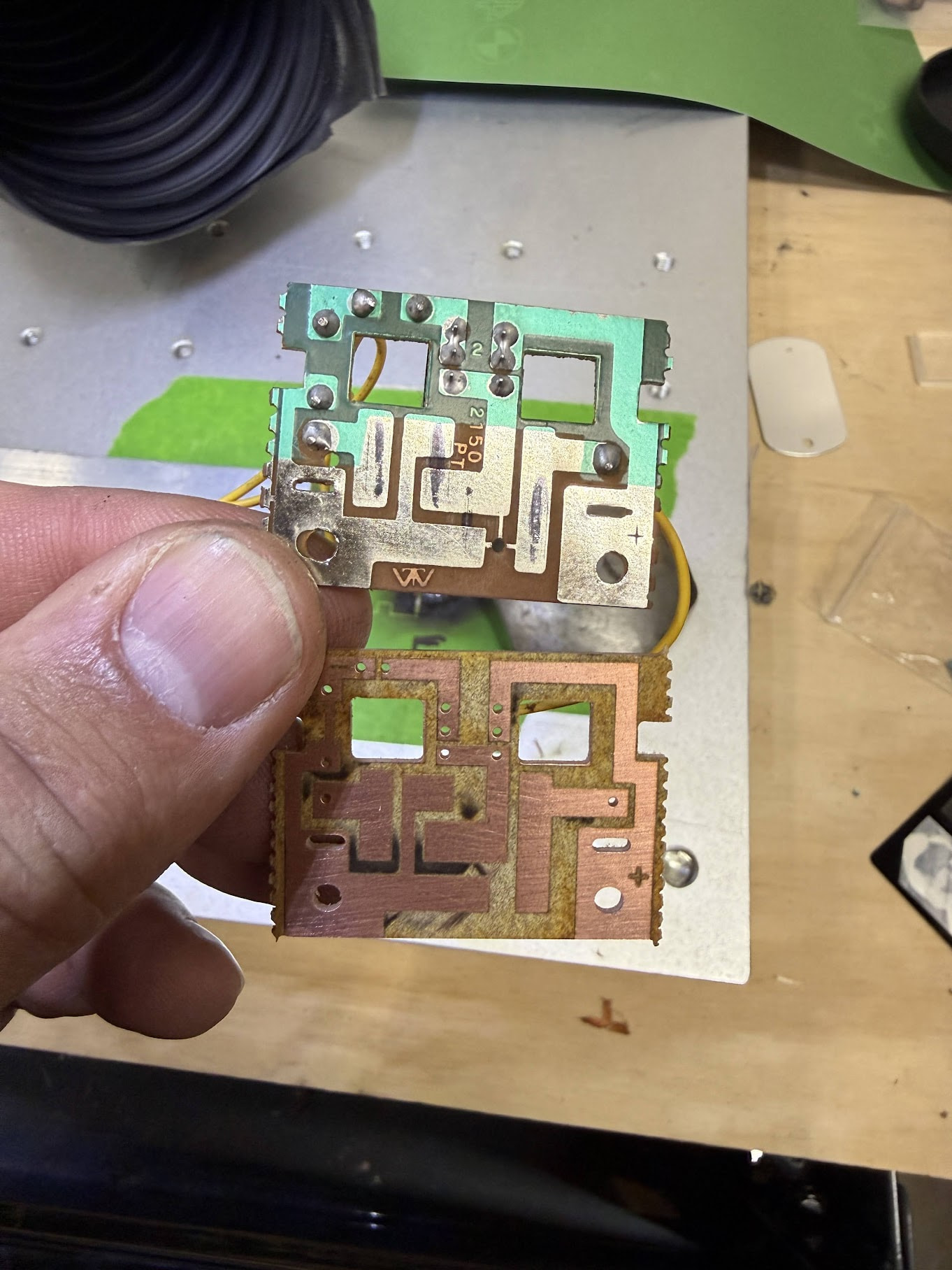
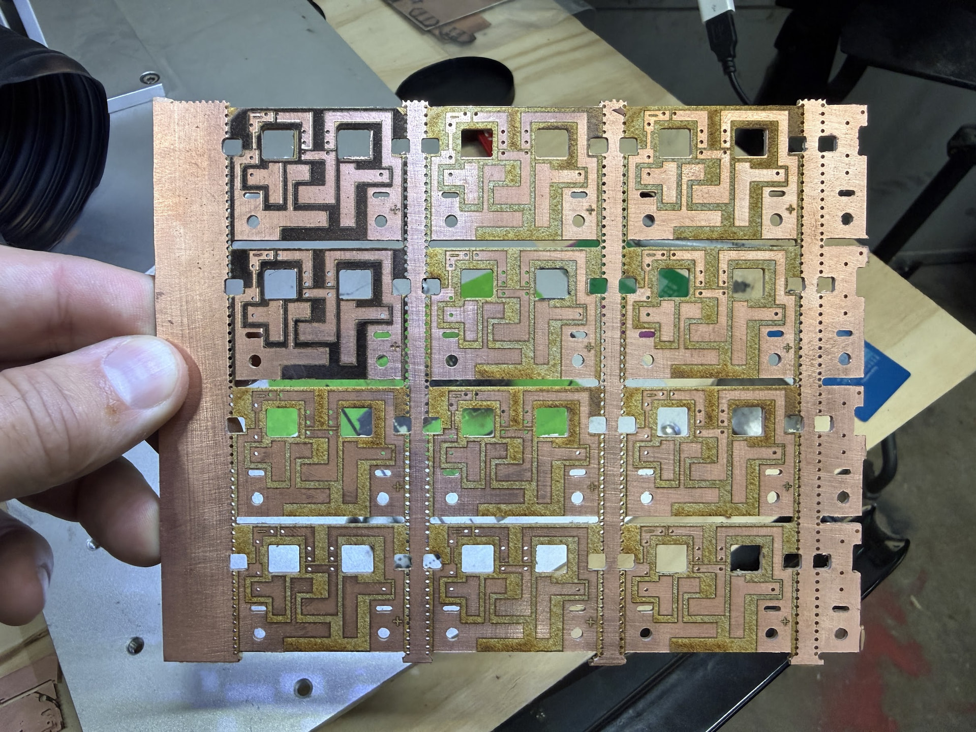
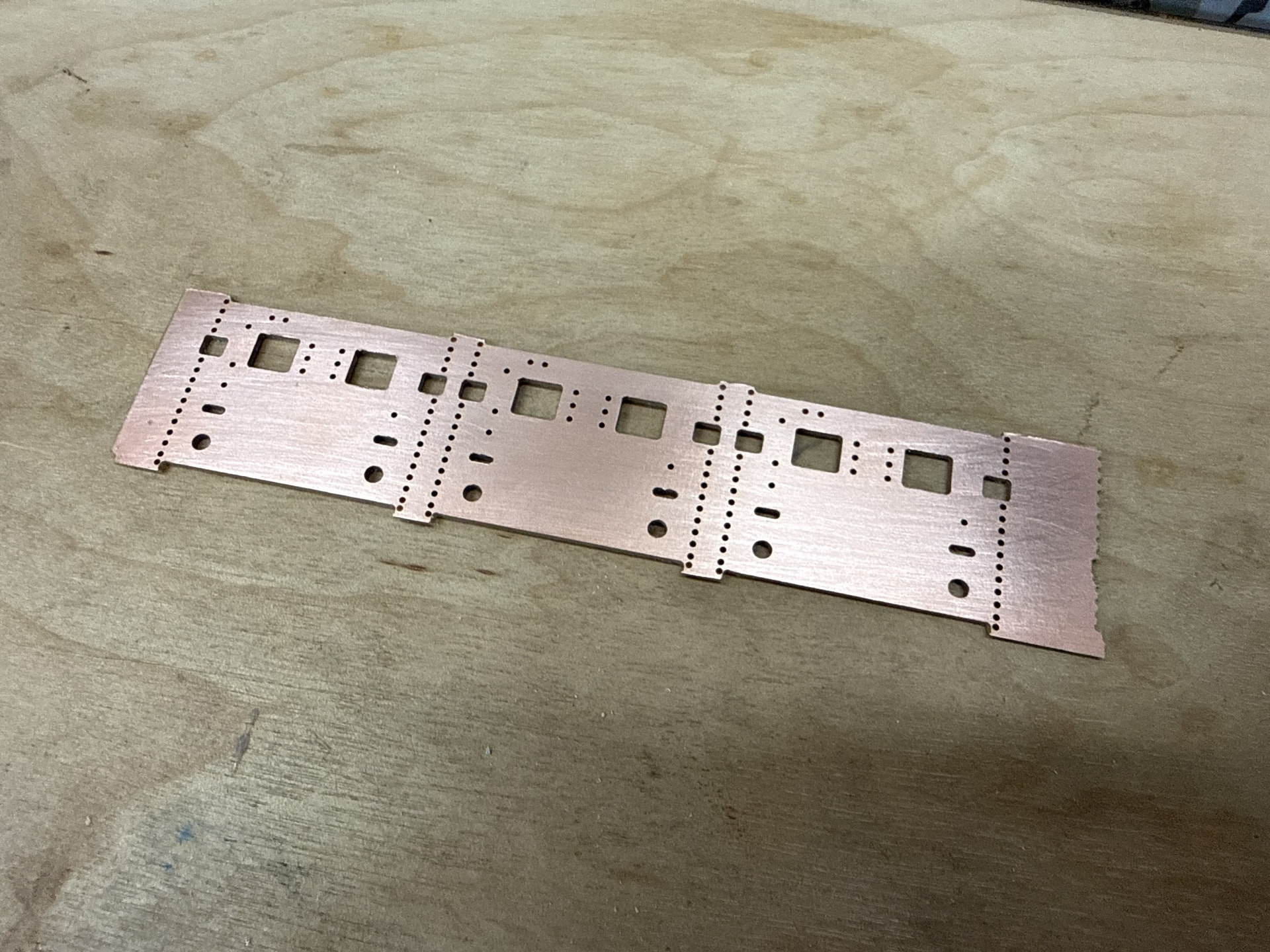
I have had success with PCB etching but it has taken using a MOPA Galvo Fiber laser to really be able to etch and ablate the copper in a way that is consistent. This process uses both MillMage and LightBurn to do the full process of drilling, routing and removing the copper.

Laser Used: 50w JPT MOPA Galvo

Line Settings:

  • Speed: 750.00 mm/s
  • Pass Count: 2
  • Power Max: 100%
  • Frequency: 25khz
  • Purpose: Create a cut line in the copper to separate the copper that will remain and copper that will be ablated in the Fill Layer Process.

Fill Settings:

  • Speed: 750.00 mm/s
  • Pass Count: 2 (single pass will leave a charred look, second pass cleans up the area)
  • Power Max: 100%
  • Frequency: 25khz
  • Line Interval: 0.0250mm
  • Lines per Inch: 1016.000
  • Scan Angle: 45deg
  • Angle Increment: 90
  • Purpose: Ablating and removing copper in the areas that need to be non-conductive.

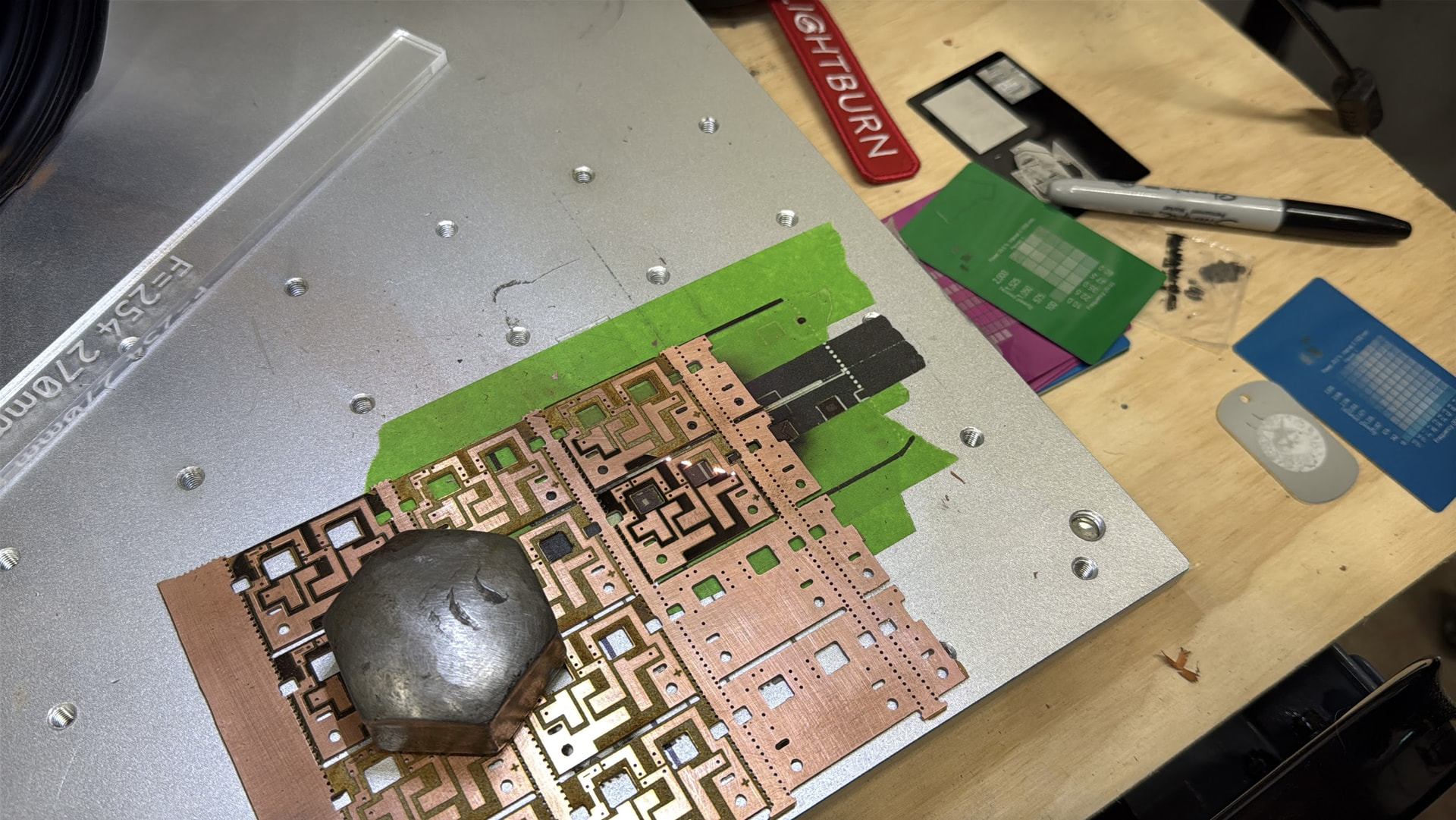
Focus is very important to maximize the strength of the beam. Copper is one of the harder materials to laser etch. I have tried doing this exact same board on a GWeike 50w BSL Fiber but was not able to get a consistent line cut or etch. Make sure to proper ventilate or filter during etching as you are vaporizing copper.

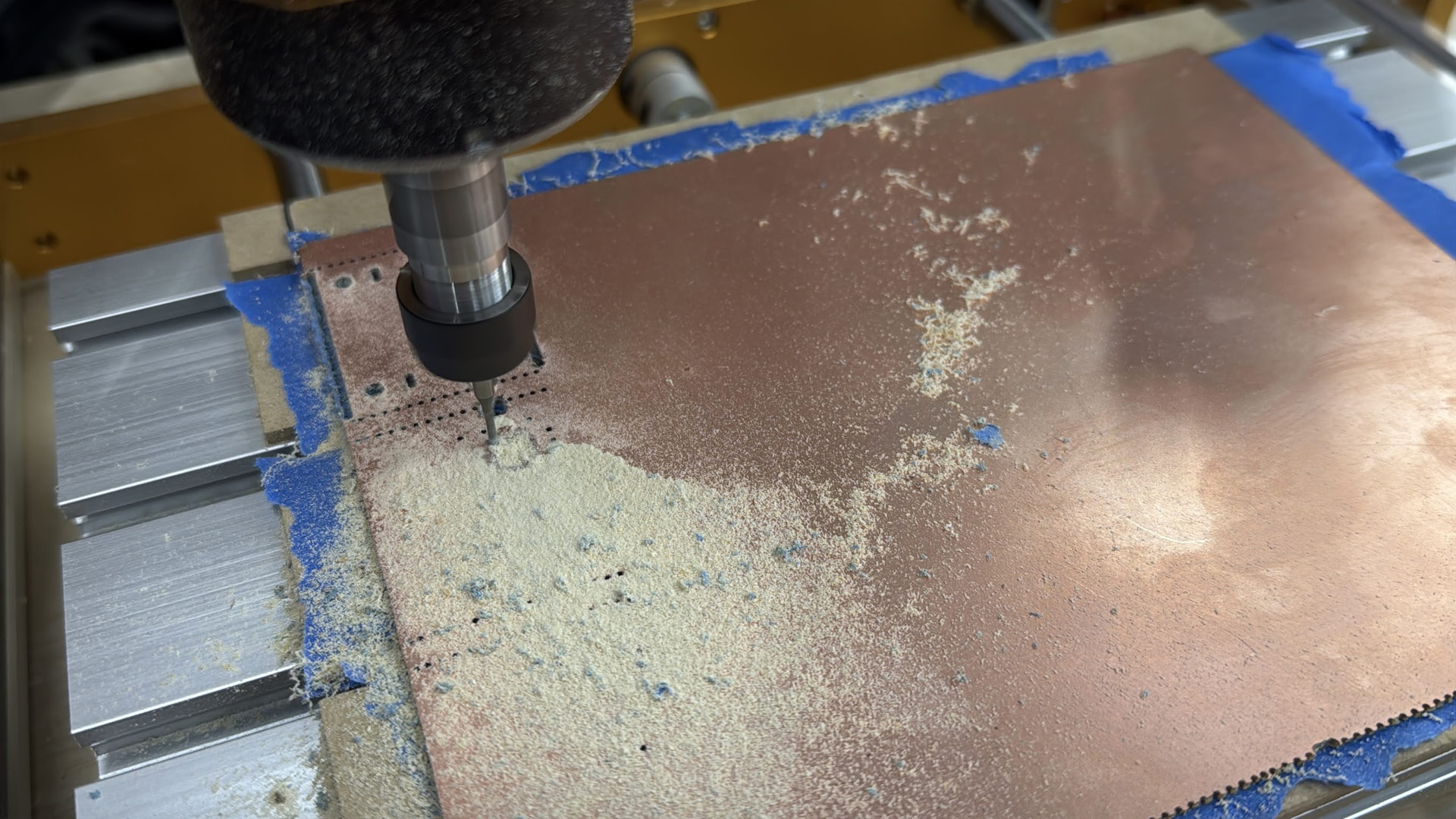
Drill and Routing was done with MillMage on a 3018 Pro CNC Router using a 1mm 2-flute drill bit (Union Tool NEU1.00MML009W) and a 1.5mm Burr End Mill for PCB Routing. The 3018 Pro CNC Router is the perfect little machine for fine work like this. Make sure to have proper dust collection as the burr routing will generate a very fine fiberglass dust that easily travels through the air. Outside of doing a vacuum table the next best hold down I have found is using painters tape on the table and back of the PCB board, then applying super glue between the tape layers to hold the PCB down for cutting. A vacuum table would be the most ideal hold down method but I have not gotten around to cutting a vacuum table yet and sourcing a vacuum pump.

Other hold down methods I have tried with PCB routing…

  • Basic clamping: Issue here is the boards have a tendency to pull up in a burr end mill. On the edges it was fine but cutting a larger area (e.g. 150mm x 200mm) the middle would pull up into the bit when milling.
  • Carpet tape: Carpet tape is a 2 sided membrane tape that typically is reinforced with threads running through it for reinforcement. It is very sticky and work great for holding down an object to the bed of a router. The But… It sounds great until the bit gums up and/or you have to remove the adhesive. Other applications this is a good technique but when it comes to PCB routing and the style of end mill you use, it is very easy to gum up a burr bit with a style of adhesive like carpet tape. Also there are issues with flatness to the table, especially if you get a bugger of adhesive which is not uncommon on the edges of the tape.

Next Steps to finish these boards will be tinning the copper using a thin layer of solder paste and heated air to protect the copper from oxidizing. I will likely be making a metal screen to apply the thin layer of solder paste just like you would do for surface mount components but instead for this to cover all of the traces.

Once tinning is done, silk screens will be made and solder mask will be applied to these boards.

6 Likes

Great stuff, Josh!

I’m surprised that the results with the MOPA were so much better than with the Gweike fiber (also 50W).

What Q-Pulse settings did you use on the MOPA?

1 Like

This machine is a little older and doesn’t have Q-pulse which makes it strange that the GWeike struggled but this machine did great. It’s like a MOPA “lite” machine, at least that is how it was explained to me. I want to get my hands on a true MOPA with Q-Pulse to see what I am able to do having that control compared to the current machine I am etching my boards with.

Side note… you may be asking yourself “what is he making?”. This is a replacement circuit board for a 38 year old kids train set that I had as a kid and am restoring to give it a second life. I am reproducing the original circuit which is very basic. Hooks up to a motor, switch, LED w/ resistor, 4 C-cell batteries. There is a slide circuit that reverses the polarity of the motor to change it from forward to reverse. I have modernized the circuit so you can run an inline resistor on the LED or if you want to go old school you can cut a trace and do a through hole resistor. Also the switch through holes have been adjusted for a modern version of the switch.


Original board: Top, Modernized version I created: Bottom

5 Likes

Interesting. The way I saw it was that even a Fiber source has a specific Q-Pulse (time during which the energy is being released) - It’s just always fixed.

I may need to reconsider what it truly means to be a genuine MOPA.

1 Like

I don’t use mine for FR4 type boards, the resin base has fiberglass strands and produces gasses that are not good for you to breath, as if anything from a laser is good to breath.

How do you align the part with the coordinate system of the CNC3018?


@Aaron.F The MOPA types allow for varying the number of pulses/S (or pulses/mm) using the frequency. Many of the non-MOPA fiber lasers have a very small adjustment range in terms of pulses/S, my MOPA you can adjust the frequency from 1 (CW) to 4,000kHz and the q-switch on time up to 500uS. This is the laser source manual for my MOPA, they seem to indicate there is only about 16 or so wave forms available.

It takes time to pump up the fiber, so they have a threshold value where there isn’t enough time at that selected pulses/S to allow the machine to fully pump the fiber. When this occurs the machine won’t produce a full power pulse. The advantage of a 100W machine is it pumps up the fiber more quickly and will pump up the fiber in 1/2 the time as a 50W machine.

The q-switch laser can operate pretty much on it’s own when the fiber reaches a certain level the Q drops allowing the pulse to occur. This is how the small IR (2W) work, the Q is high until the amplifying cavity pumps up, then it’s released.

I’d suspect it very similar to how all fiber machines work, but a MOPA has more control over the pulse occurrence and how long the Q is low.

As you get more deeply into how these work, it takes lots off education on the physics involved and how the fiber is made. I’ve been told there isn’t much you can change in the manufacturing end to change the fiber itself.

Q-switch is the Q of the circuit, just like any electronics a high Q is lots of resistance to the frequency and a low Q allows more of it to pass. Just like a radio uses with it’s filters.

From what I understand the seed diode controls the pulse width and frequency. This is from JPT, I like the video as it’s more where my interests are.

There is a lot of information on how the Q switch or switching on a MOPA works or is constructed, so I’d have to advise you google it for more details.

Hope this helps.

:grinning_cat:

3 Likes

This boards perimeter, notching and holes made alignment/scaling easier in this project when framing the board on the galvo through LightBurn. I have another project I am just starting that will show batching of boards and with that one I will be adding alignment markers to help align the boards between drill/routing and lasering. This board I posted here is replicating a 38 year old PCB so I calipered all of the pads, holes, etc and CAD’ed them out. The notching on the boards made aligning processes easier between MillMage and LightBurn. Also it was CAM’ed out in MM and LB on the same base drawing. The next project, which I will be posting as well, will be honing in more on a project out of KiCAD brought into both MillMage and LightBurn to then create a set of PCB’s.

Next project is making an interface board for a 3D printer print farm where you can ready a printer through a button press, get status and a few other basic features at the printer. Considering it being a two sided PCB project. I will be documenting the whole process/steps and posting it now that I know it is possible. The board I posted has been something I have been on and off tinkering with for a year because I wasn’t confident it was possible. Now that I am, I want to document everything to be able to share and replicate in the future.

Fiberglass/resin laser fumes… Yes they are not good to breath. There is a charcoal filter actively pulling fumes from the ablation process. Proper ventilation is important doing what I am doing in lasering off the copper and getting down to the fiberglass core.

1 Like

Definitely helps me. I (Electronice Instructor) taught the basics of pumping a Ytterbium crystal to get a laser many years ago. New application for an old concept. And today’s manufacturing technology makes them so much more efficient. Thanks!