My plan is to produce PCBs using my laser-engraver. I am using DesignSpark for editing the schematic and board layout, and load a negative image into Lightburn for burning black paint off the pcb where the copper needs to be ettched away. I am still just tryng to get it work using examples. I would prefer to use gerber files, but lightburn does not support it, and I haven’t found another (free) app that does,
I had trouble with pdf files. t got a lot help from designspark support who came up with this:
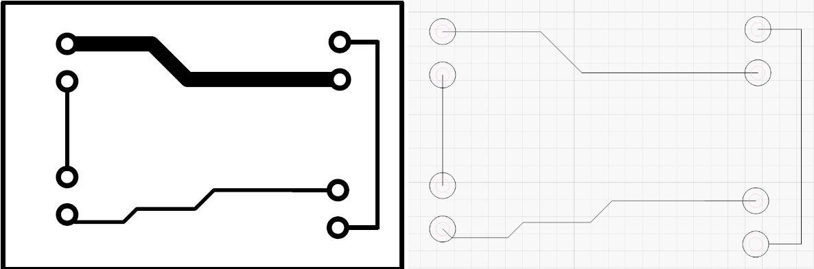
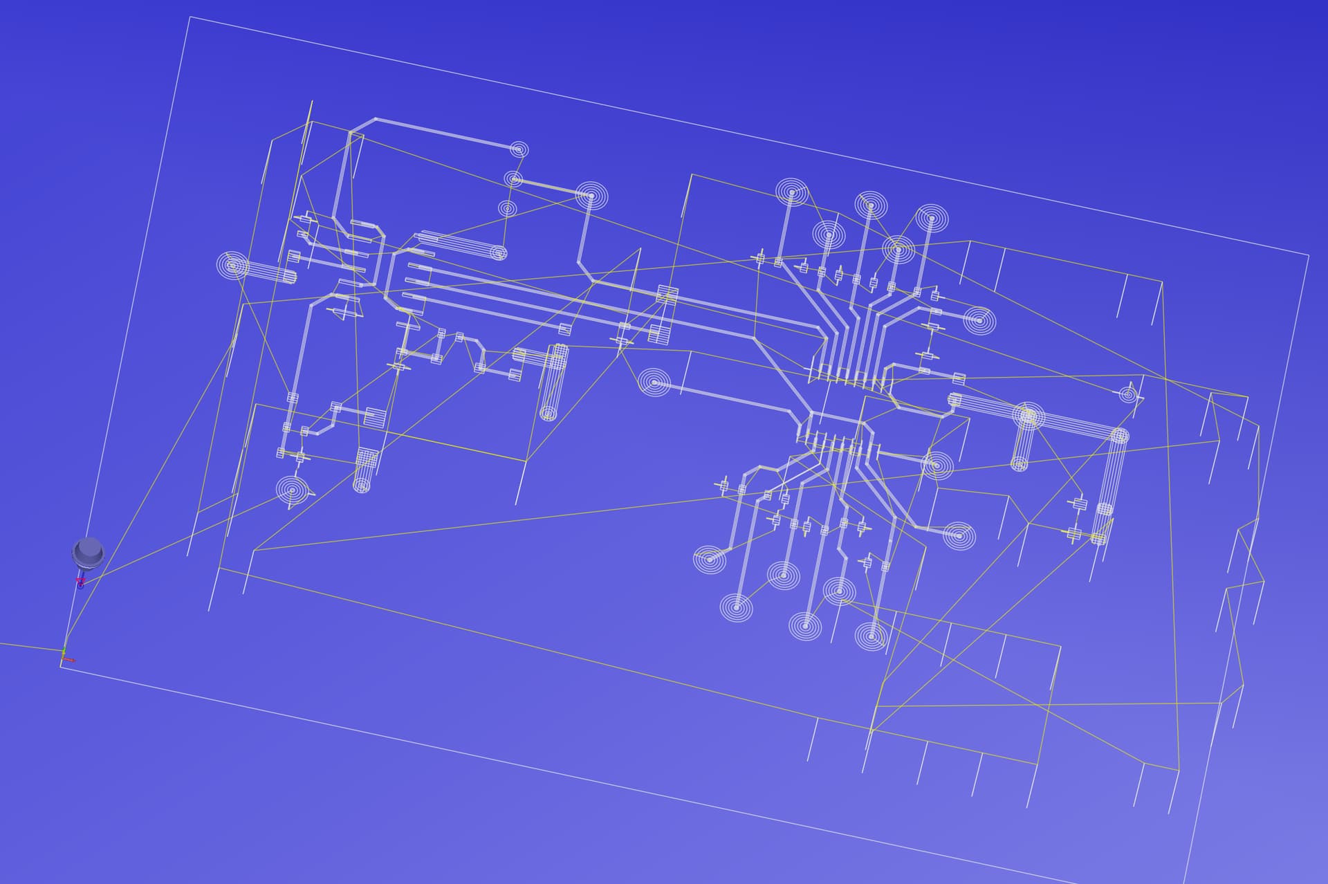
Lightburn is importing a PDF in what is considered to be an “Outline” mode. In this mode the PDF is minimised to NOT using a line width, but shows the path of a line, so tracks are reduced to single line that you observe.
It is slightly confusing when working with negative plots as you do get the outline of the large negative (black) area. As this is a continuous shape, if Lightburn is set to “fill” the area will appear black, but this is just due to the shape being continuous unlike the single line of a track.
I also tried another PCB CAD program EasyEDA and the results were the same as DSPCB and Pro.
The Lightburn import is on the right showing the issue.
I could not find any setting in Lightburn to resolve the import issue, so I explored other options.
For the PDF I could not any solution, examples I found were all related to “text” and all seemed to have issues.
Possible Solution.
I next explored any conversion options in “art” programs and may have a usable solution for you to explore further…
I used a free program InkScape,https://inkscape.org/ this will open the PDF file and retain the high quality vector image.
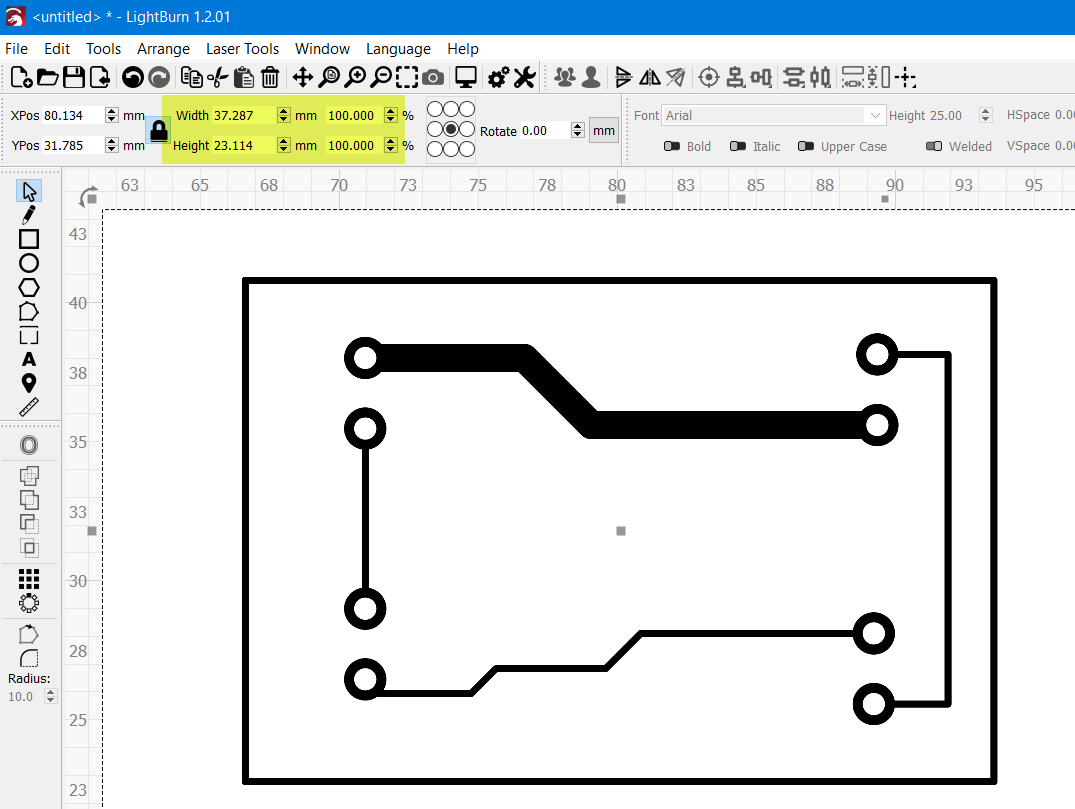
Next I selected “Export PNG” and you can set the DPI as you require and convert the PDF to a high quality PNG file, I chose 2000 dpi and when imported into Lightburn was shown as below.
As you can see it’s a high quality image!
Any jaggies you see are the current screen display rendering, if you zoom in on an area they are smooth lines.
BUT the size is large! In Lightburn you will be able to scale with the highlighted tools to exactly as you require.
You are latched on the image as intermediate step. You should avoid it.
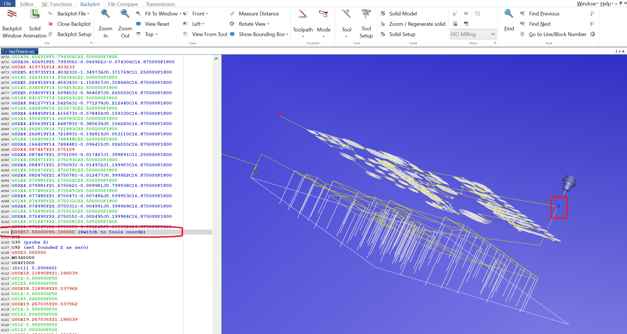
I just did this Gerber to NC conversion. It fill toll path for isolation milling/burning and even did drilling with one path, nicely swapping tool in between. That drilling you may cut and paste or just delete. This is one stop conversion. It is free. When I convert - it did complain about some complex polygon, but result is fine.
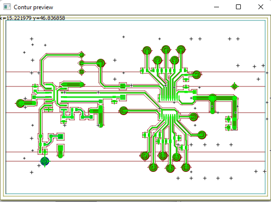
Back-plot of my trial is below.
If you like - drop your Gerbers here - I will try to convert to NC.
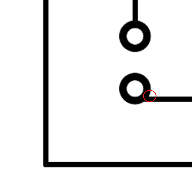
This is considered error, copper angle sharper than 90 degrees, called Acid Trap. It may cause accelerated etching - thinning of the lines. Reroute to the center.
I downloaded PCBconverter and it works fine. DesignSpark, that I have used for connecting to the laser-engraver unfortunately does not support .ngc files. Do you know of one that does?
G-code may have different letters for file extension, but they all are G-Code. Rename NGC to NC or just G. Most laser software will be able to open it.
You may use “UGS” to send code to machine. I think LightBurn should be able to send NC files.
I would recommend to post process your g-code in text editor, maybe, if any problem, to get rid of Z-motions and such. But g-code is g-code, mill or laser or CNC.
From Digispark you should get Gerbers, this is the standard, not NCs or PDFs, then convert them to NC (NGC), ideally also checking it with backplotter (here is the one I really like), then send NC code to the laser, with LightBurn, or UGS or any other software that can send g-code.
Note that this software will also convert Gerber drill table to g-code, very handy if you have combo machine like 3018 CNC.
I tried renaming th file, but Lightburn does not recognize it in ‘open file - all supported’. So I tried renaming it to .sc which is showing in 'all supported, but same result. It is recognized in File Explorer as ‘Gcode for laser engraving’ but Lightpurn ‘Open’ files does not see it.
I would expect LightBurn to be able to run NC file.
You cannot edit NC filed in LightBurn, only send to/control your laser machine.
You may also try UGS or LaserGRBL.
I got a ‘Enjoywood’ laser engraver fairly recently, and so far have only found laserGRBL and Lightburn working with it, and in Lifhburn Device list I onl see GRBL, GRBL-LPC and GRBL-M3 (I assume it must be a GRBL something).
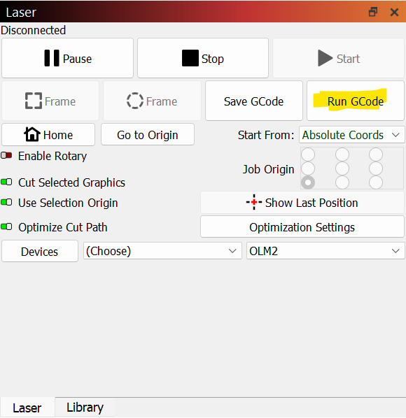
Yes, exiting beginner mode unveiled the ‘Run GCode’ button in Lightburn. I as then able to run a gerber file of a pcb I created myself, but still so much a beginner I would like to try an example first, However I getthis error every time: 'Unimplemented commands G36/G37(Polygons). I tried usng an examl from Designspark.
Run this in Console to determine your grbl version for the controller:
$I
Unless the board is very old it’s likely 1.1f or newer which means you’d be better served with GRBL vs GRBL-M3.
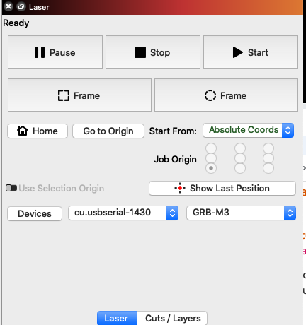
To confirm how your device has been setup in LightBurn can you click “Devices” button in Laser window, then click once on the name of your laser. The device type will show at the bottom of the window. Can you take a screenshot of that?
I had this popup. Usually ignoring it, checking with back-plot and never seeing any problem.
I guess it is a possibility that it may actually affect something. Worst case - gCode can be edited a bit by hand.
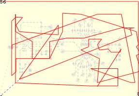
I am still having trouble creating a pcb. I created a gerber file using an example in DesignSpark. I then used PCBConverter to create a gcode file. As mentioned before, when I load the gerber file into BCBConverter I first get a pop-up saying “Unimplemented commands G36/G37(Polygons)”. When I click ‘OK’ I get a second pop-up saying “Diameter too small”. It then gives me this preview:
It looks a little weird to me, but I don’t know what good gcode looks like. I change the file extension to ‘.nc’ and when double-clicking on the filename it brings it up in LaserGRBL, but also looks weird:
LaserGRBL runs on the file, but doesn’t turn on the laser, and the console shows a lot of ‘unsupported command’
In LightBurn I can select the .nc file with ‘run GCode’ but nothin else. The ‘Frame’ and ‘Start’ buttons are greyed out.
What am I doing wrong? Is there software that is better to use for this?