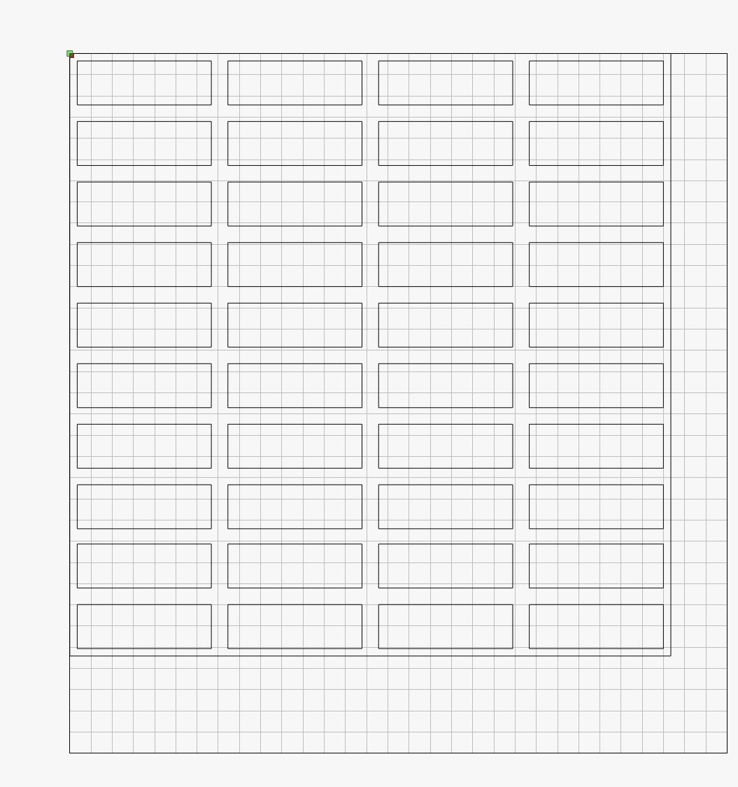
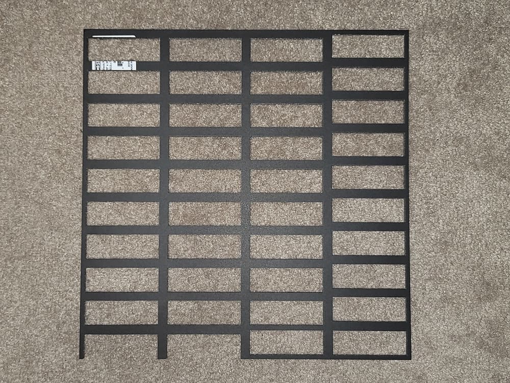
I have made a file in Adobe Illustrator, exported it as an SVG. Imported it into LB. Created a width x height total square, enlarged it slightly and of course centered it all. Here is what my LB looked like.
The perimeter spacing is 3.5mm however the spacing is actually 3mm (thinner parts) - why is this not cutting as actually 3.5mm? The same for the right side. When you start looking around there is a whole host of issues.
Column one is too low, and the entire column was shifted down into the perimeter below, causing it to cut incorrectly.
Column two is too low down, same thing.
Column three is good, but the spacing at the top is 2x what it’s measured to be, and correct on the bottom - but only for the fact that the vertical spacing of column three at the bottom, is now wrong. Notice the gaps as you go down, they get thinner on the last two gaps.
Column four is doing it’s own thing, but it’s the correct distance from the perimeter top, right and bottom sides.
How can all these cut so wonky when the file is perfect?
Thanks for taking the time to reply! I have attached my LB file and the SVG.
This is likely not an issue in the design as far as alignment is concerned. This is most likely a mechanical issue possibly coupled with a configuration issue.
First thing, your profile is vague about your actual hardware and likely wrong about the controller as Ortur lasers don’t use Ruida controllers. Can you absolutely confirm your laser model? If you’re having trouble identifying it please take a picture and post it here. The specific laser will change the type of advice you get here.
Once you share that we can troubleshoot some more. Can you share any background on the laser? How long have you had it? Is this your first test or has it been working? Were you the one to assemble it? Anything that you can think of to provide context would be helpful.
I apologize for such a vague description. This machine was passed onto me, but built by my bother (who has now moved onto a 4x8 ft CnC routing table).
It’s approx a 2.5w diode - a chinese one. It’s been ages since he bought it. That’s all I have on it sorry. It’s also got no defining characteristics on the physical laser itself.
The controller board is a grbl cnc shield
The frame + everything else is (he believes) a makeblock xy plotter
This is his and my first laser. It worked wonderfully for him when he had it. I should give a little information here however. I can cut incredibly delicate cuts on any medium (that it’s capable cutting) with such intricacies. Upwards of 2 hours to cut. The issue arises when it’s repeating patterns only so far it seems.
Another example was I made a line (I designed this INSIDE LB to eliminate the crossover of Adobe Illustrator into LB) that was 50mm long. I then copied it, and pasted it the same place. Moved it down 10mm, rinse repeat. I did this until I had 20 lines. I then copied this, and rotated it 90’ to have a grid pattern. I (at the time) was testing a weaker output of the laser to see if my bed was totally level since I have no Z axis. If the grid was burnt dimmer in an area, the bed is either too high or too low in that spot.
What’s weird is, as the laser starts moving downwards to cut the horizontal lines (again, they’re IDENTICAL) and did the cut/burn, the lines got progressively longer. Like, an extra 1mm, then 2mm, then 3mm to a point where the line was about 20mm longer than the very first line cut - but again in LB, they’re all copies of one another.
It seems much like the squares above + this line example I mentioned - when it’s a repeating pattern, LB messes it up somehow. Throw in 500 cuts of a beautiful peacock and feathers and it’s immaculate.
From what you’re saying i tend to think the issue is purely mechanical, not configuration or design related.
It seems like you’re missing steps somehow. Your speed in the design doesn’t seem excessive so I assume this is not the issue unless there’s something specific to your setup. I would suggest first checking your belts for proper tension, particularly on the Y-axis. The belts should be taught with no slack but should not be stretching. Check for any binding as well. The laser head should move very smoothly and with little force.
While you’re checking tension examine the belt teeth to make sure none are damaged or missing. Make sure you’ve got good engagement with the pinion on the stepper motor. Double check that the pinion has solidly attached to the stepper motor with no backlash. Recheck the grub screw to make sure it’s well attached.
In the meantime, can you run these commands in the Console and send back the output results?
Unfortunately I don’t. I threw it out as I thought maybe it was just a weird glitch. Then as I progressed into other repetitive patterns, it continued to be wonky. I tape my material down as well so there’s no chance of material moving. The command lines came back with
I don’t see anything really outrageous in those settings. A few things that stand out to me:
$22=1 sets the homing cycle to happen but $21=0 indicates no limit switches
Do you have limit switches installed? And does the machine home at start?
$10=0 might be an indicator that you’re not homing and relying on machine-on posiition
$120-$122 - These values at 1000 are not high in absolute terms but I’ve noticed these tend to be lower for CNC based systems. This possibly could be contributing to stepper misses if being asked to accelerate too quickly.
Out of curiosity, can you also run a $# and paste results here?
Okay. Let’s separate out the configurations that might be related to the missed steps from the other ones that you might want to explore further down the road.
Potential stepper skipping remedy:
$120 to $122 set your acceleration (mm/sec^2) for X,Y,Z respectively. I believe these are set to 10 mm/sec^2 for Sainsmart machines. I suspect it’s because those type of multi-purpose CNC machines are carrying a lot of mass on the gantry and mounting system. Your setting at 1000 mm/sec^2 is perfectly in the norm for diode laser but I’m not familiar with your specific setup.
I suggest you first work through any mechanical issues before exploring any changes here. If and when you do I strongly suggest you take a backup of these settings in Edit->Machine Settings first.
Non-critical changes you may want to consider in the future:
$20=1 - This will set soft limits; so once homed it will use your working size info from $130 to $132 to prevent you from going beyond these limits. You will get a soft alarm in that case and can prevent a crash.
$21=1 - This sets your hard limits; not sure if this was changed to disable the ones on the right and front but this would do it
$10=1 - Right now this is set to 0 meaning that you’re working in Working Coordinates, not Machine Coordinates. Normally you’d work in Machine Coordinates if you have homing enabled. In practice I’m wondering if these are the same in your case since I don’t see an offset set for you from the $# information.
Thanks for this reply! Sorry for the delay in a reply I have been crazy busy. I haven’t done what you suggested yet, but I thought I would mention something that happened that may provide more insight.
I opened up the exact same cut file. I figured I would rule out a weird oddity glitch and cut again. All the columns were perfect, except the first column (which was cut last). It seems to be rather random. Perhaps something belt related indeed but I won’t know until I am able to test the belts, perhaps even replace them. How much tension should there be?
Get to it when you get to it. We all have lives to live.
For the belts you don’t want any visible slack showing. At the same time you don’t want the belts actively stretching where it’s deformed or sprung. Main thing is to remover any slack at every articulation point of the belt where it touches another part of the machine.
Yes. At least until you rule out acceleration as an issue in the problem. Others with your laser type list 10 for setting. Would be nice to get confirmation of what manufacturer recommended value is.