I’m trying to minimize doing a material thickness calibration (Calibrate Camera Alignment) for each material thickness that I work with.
The way I do this, is for example if I did a material thickness for 16mm material, and I wanted to do a 3mm material, as long as the material I’m engraving equals 16mm in height, it works.
What I specifically do is I take some scrap material and boost the height of the material I’m engraving to equal to the 16mm(as this is my calibration which I loaded). All works perfectly, so I created a few material thicknesses, which gives me a spectrum for many material thicknesses. I do a 3mm, as my most common, then a 10mm, and then a 18mm, which I never go thicker than that.
The other thing I do, is measure from my laser module to the bed minus the material thickness, which in this example I had a 16mm calibration loaded, this gives me a number, as long as I my material which I’m engraving is this measurement, it works perfectly, so with a bed that lowers, such as using an Xtool S1 riser base, I can do wood bowls the same way, without having to do many material thicknesses.
My question is, if there is a way for the camera calibrate file (LBCM) to be manipulated such that when calibrating, a material thickness(Calibrate Camera Alignment) is given, then this calibration file can be manipulated using logic based on a new material thickness.
Here is a Video where I demonstrate the first method
I’d say that is obvious. If you calibrated the camera for a specific image plane, it will always work, no matter how thick the workpiece is, if you raise the workpiece to the calibrated height.
And with a height-adjustable bed, you never need to calibrate again, since the image (focus) plane always is the same. That’s clear as well.
So, I think your video does not explain something new, just mentions things that are obvious and common sense. Though, it still might help some people because many users don’t have much technical thinking. So explaining it once again might help the community
No, that’s not possible. It’s not a simple calculation. In theory you could create a calibration like this, but you would need a more complicated calibration procedure beforehand. With the calibration as it is, you only get a relationship between image pixel and workspace coordinates. The height makes this three-dimensional. So you require exact positioning in 3D space and beam angles of the camera optics. It’s possible in theory, but since people already need an explanation of obvious facts (like your video gives, no offense), 99% of them will fail to accomplish this calibration.
Thank you, A lot of folks do not realize what I described in the video. I get asked all the time, how to save time, by not having to do a calibration for each material thickness. So, this is why I created that video, as they did not understand the relationship as you described.
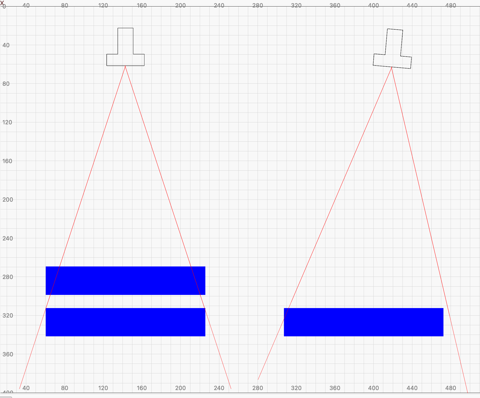
Sometimes it is easier with a simplified sketch to explain what is happening and why a static height and angle are crucial for precision with the LightBurn camera system.
In the example on the left you can see the (exaggerated) influence of the height and on the left the influence of the angle orientation in relation to the result.
Some height and camera angle combinations are less exposed than others, but the problem is always the same.
I don’t know if other manufacturers of camera solutions have better/different solutions for camera handling, X tools new laser looks very interesting in their promotional videos, but how precise they are I don’t know. But it could look like they have found a better focusing and exposure handling…, in their videos