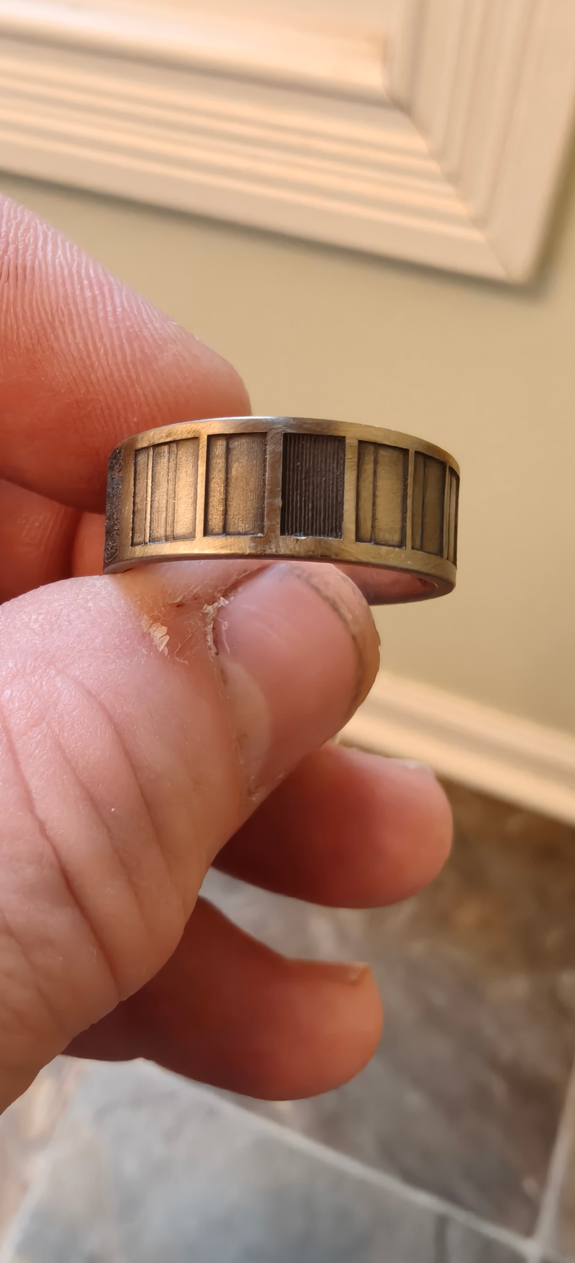
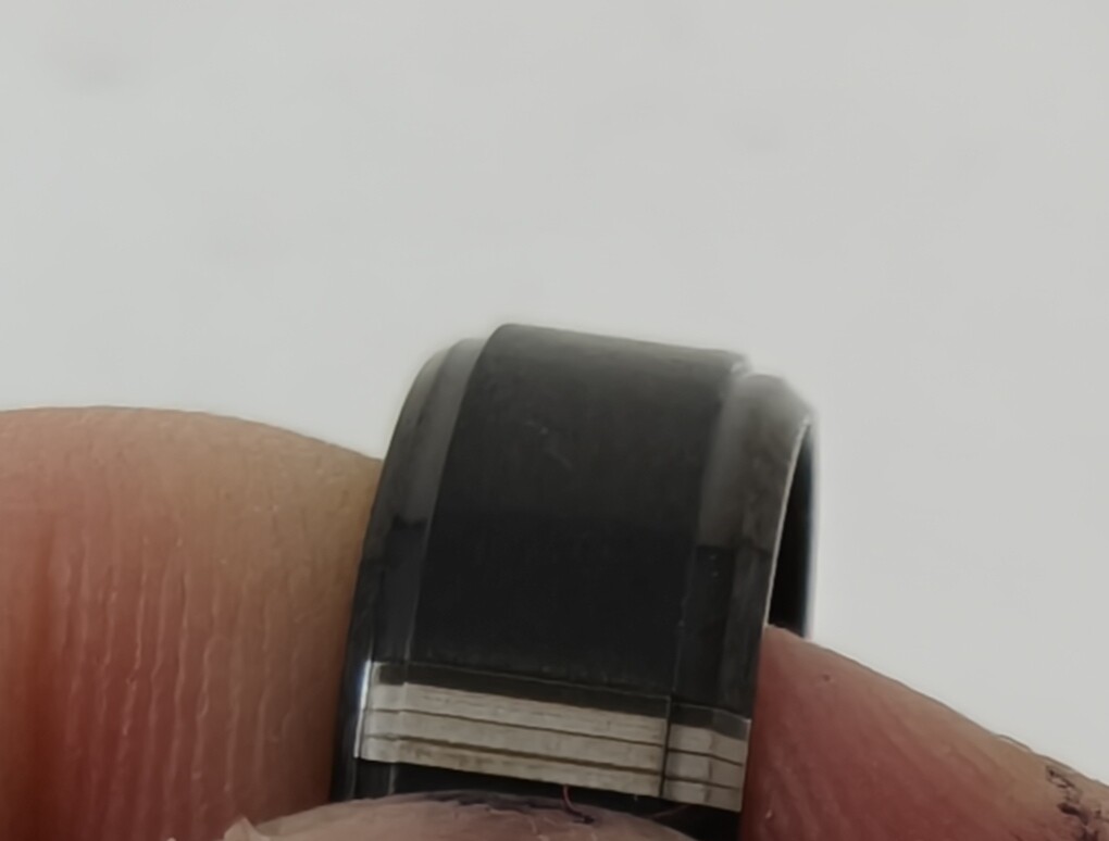
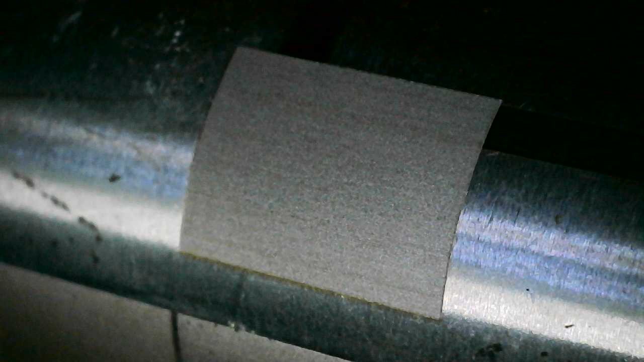
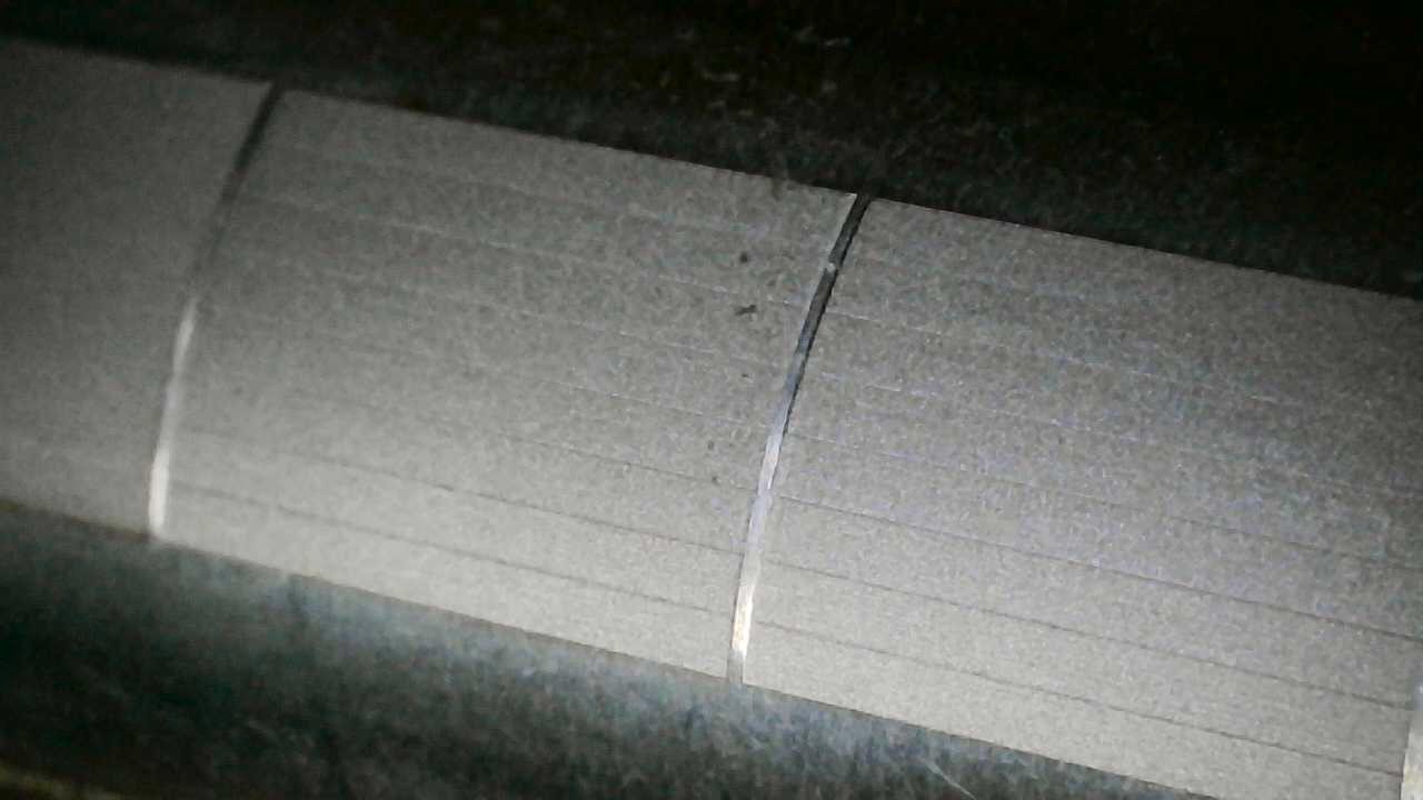
I am experiencing a persistent issue when deep engraving stainless steel rings using the Galvo rotary mode in LightBurn. A distinct raised band (appears as a skipped line or area where the laser failed to fire) occurs precisely at the boundary marking the start of each new slice immediately following a rotary movement. This happens consistently on simple test shapes (like rectangles) that span across slice boundaries. No matter what I do, that gap between the slices remains. The size of the gap never varies as well.
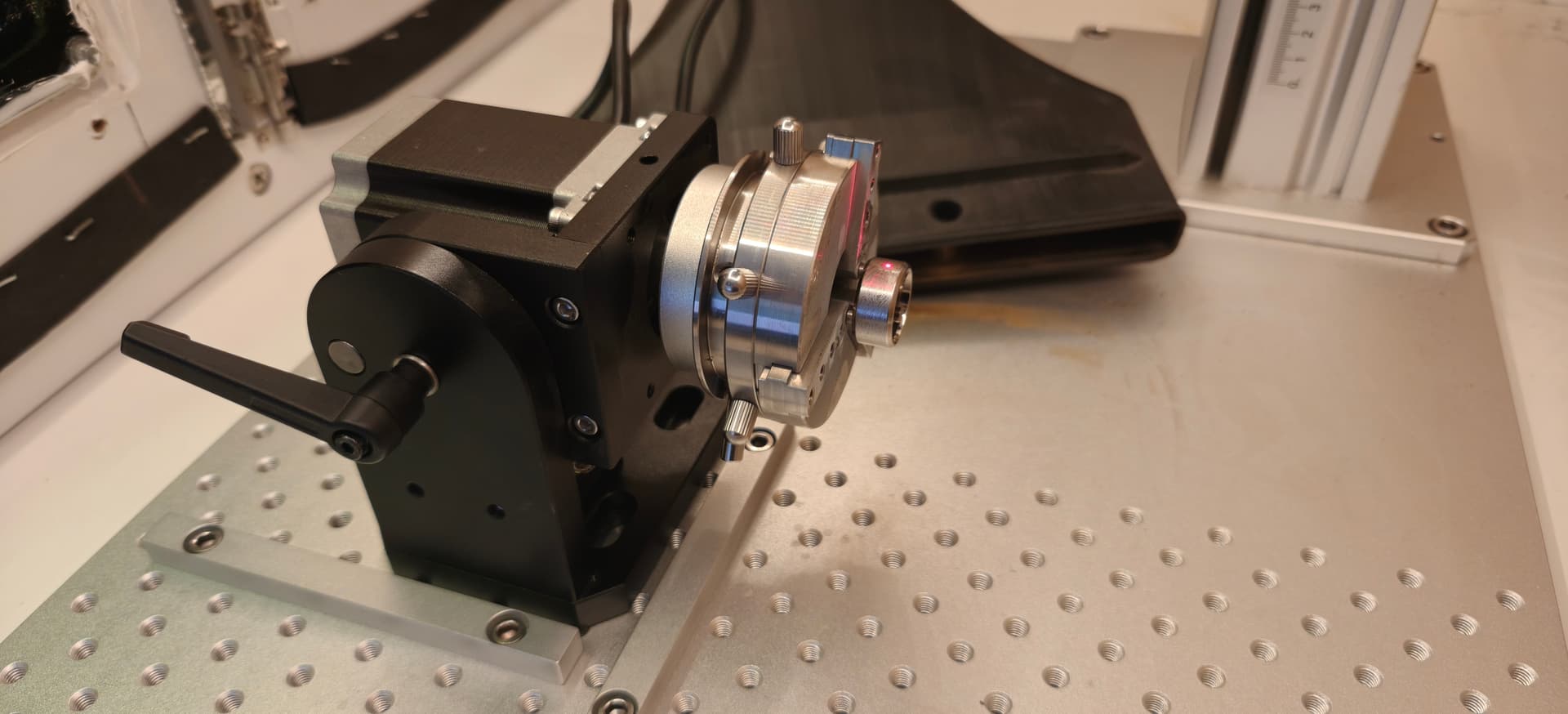
This is on a Haotian 200W JPT MOPA Fiber Laser and the rotary is using a Snowit stepper motor.
The band is raised, indicating the laser did not mark that area, rather than an overlap or misalignment issue.
It occurs on the very first pass and persists through multiple passes.
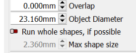
The raised band appears regardless of the Overlap setting in Rotary Setup (tested 0mm up to large values; large values add separate burning artifacts, but the original raised band remains).
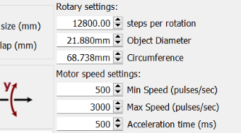
The band appears regardless of the Split Size value. Tested both 1.178 mm and 0.177 mm; bands just appear closer together with the smaller split. *Both tested Split Size values were calculated to be integer multiples of the rotary’s surface step distance (Circumference / Steps per Rotation).
The band appears regardless of the Laser On TC delay setting
The band appears regardless of the Laser Off TC delay setting (tested 250 µs and higher values).
Changing Rotary Motor Speed/Acceleration settings in Rotary Setup did not resolve the issue.
changing shape options did not resolve the issue on test shapes requiring splitting.
Using Cross-Hatch and Angle Increment settings does not affect the band at the slice boundary.
The laser can engrave correctly at the exact boundary location if engraving simple lines positioned there manually (i.e., not as part of a sliced graphic fill).
Tested with small and large positive Overlap values.
Tested with synchronized Split Size values (both larger and smaller multiples of step distance).
Tested different Max Speed values for the rotary motor (down to 800 pulses/sec).
Tested significantly increasing the Acceleration time for the rotary motor (from 100ms up to 500ms).
Tested Laser On TC set to 0 µs
Tested increasing Laser Off TC
Confirmed issue occurs on single pass tests.
Tested “Run Whole Shapes If Possible”.
Tested reversing the rotary direction.
Since standard calibration, overlay, split size synchronization, motor motion profiles, and primary timing delay adjustments aren’t having any effect on this line appearing at the slice boundaries, I’m not sure what to do next.
Sounds like you have tried a lot of different things, but you should never run cross hatch or angle increment with a galvo/ rotary UNLESS you are running whole shapes. Otherwise scan parallel to rotating axis. Don’t mess with cross hatch, angle increment, and whole shapes until you get parallel scanning dialed in.
Overlap really doesn’t help with galvo IMAO.
I would think on a cylinder that size split should be less then a mm, and agree match the circumference / microstep setting.
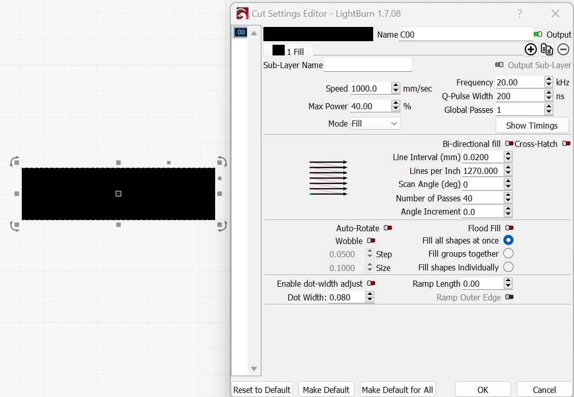
Try turning off the cross hatch and bi directional, turn the power down, and run a test scanning parallel to the rotational axis. Post a screenshot of your rotary settings and parameters (Cuts/ Layers) settings.
@breadwig You could be at split 0.537 instead of 0.540, but that is only the width of a human hair, something else is going on. I would do split .537 and LI should be .0214. Are you 100% sure your caliper is giving you an accurate measurement? Your settings look good.
Question, when you start to laser, does the rotary start at the bottom of the image and work towards the top?
You could try:
wiggling your chuck, see if there is any slop
increase the diameter, test, reduce the diameter, test
try some asymmetrical letters like d, e, f with a small split and large split.
try a different rotary.
Go back to your original settings for jump and timing
Trying to determine if this is software or mechanical related.
I tried the more exact split size just to see and still got the gaps.
The rotary starts at the bottom and works its way up.
The chuck doesn’t have any wiggle.
increasing and decreasing the diameter produced the same gap lines.
I did a test with d, e, and f with different split sizes and it just made more or less gap lines.
I went back to the original and jump and timing settings and no change in gap lines.
I don’t have another rotary unfortunately.
just to see what happened I tried reversing the rotary direction and while it messed up the letters, it also made the gap lines more prominent, for whatever that’s worth.
Im sorry im not coming up with anything good.
My last dart, try a different material, it is possible it takes a pass or 2 to bring the ring up to temperature before it marks. Try a wrap of black tape or put a socket in the chuck
Also raise your frequency maybe 40 or 50KHz
That’s kind of what I am thinking. Not anywhere near my computer now, might try changing fill all shapes at once, and change the repeat to 1. Just to see. When I do deep engraving on rings or cylinders, I mix up the split sizes and LI every few passes. Odd numbers so I get overlap.
I am assuming test gives you exactly 1 rotation forward and back, but when you measure the rectangle does it match what is on the screen?
Try changing your steps to 20,000. In the name of science.
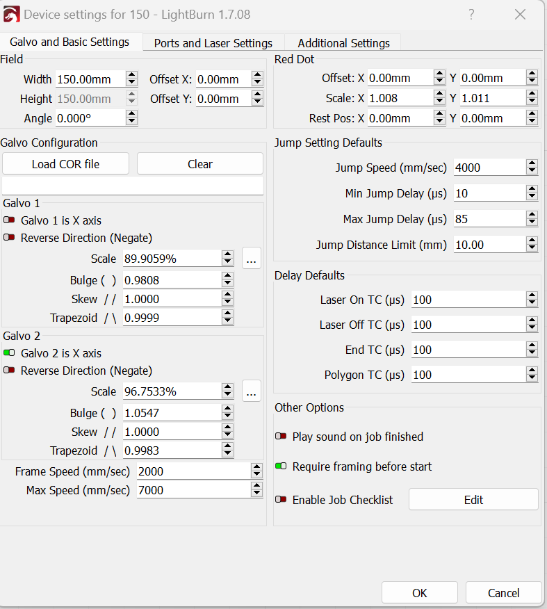
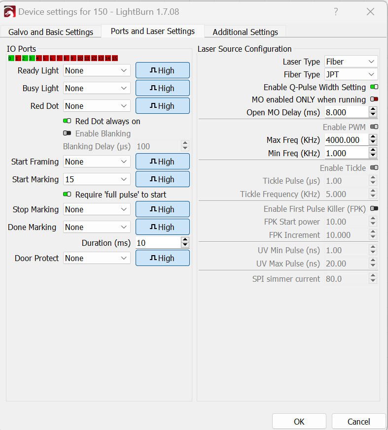
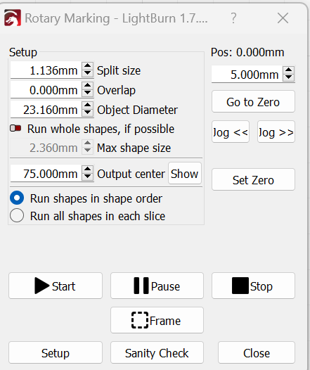
Also post screenshots of galvo settings, Ports and laser settings, the second rotary screen after the framing screen. I’m probably not going to see anything but who knows. Just throwing things out.
I have 2 regular rotaries, a rotary table, and a linear table, but never one posessed by the devil like yours.
changing to 20,000 steps yielded big gaps between slices.
the secondary rotary screen settings might look different than previous screenshots of the main rotary settings because I changed the test ring when trying a different material.
Maybe I was thinking backwards. Did you try 6400 steps? 8,000? Also, usually JPT Mopas are IPG_YLPM, not JPT in the fiber type field. Only thing different then my 60W. But I don’t see how that would matter. What do your flat engravings look like?
Ran some tests, agree IPG_YLPM or JPT made no difference. On a 1" diameter piece of stainless, smaller splits made for nicer etching. Try split size = 2 LI, and use BI direction.
This was done with a 0.020LI, 0.08 Split BI = off, , followed by 0.016LI, 0.032 split Bi = on
One pass each.
smaller splits look nicer under the USB microscope.
Second option if you are not trying a continuous wrap, use the “Run Whole Shapes” and make your max size a little larger then your rectangle height. Then you can use bi, cross, angle. Downside is it really starts to distort on these small diameters. On a ring I wouldn’t go over a couple mm.
I’m doing designs that fully wrap around the rings unfortunately.
I tried .02 with a .08 split and it indeed looks better when using just a few passes, but deep engraving with like 80 passes the lines are super visible still. Takes a lot longer to engrave too of course..