Photo engraving help needed please

I have done a good deal of research and experimentation to feel guilt free for posting this. I need help with photo (grayscale?) engraving.
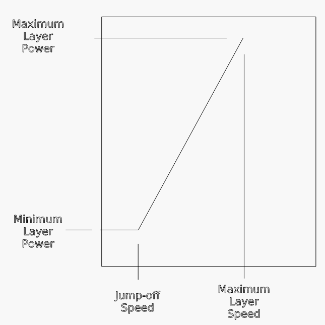
I am just trying to to get an image to be engraved onto birch plywood. Im not trying 3D grayscale… just basic image engraving, so it’s my assumption that the plywood isn’t the issue. Every time I do it, no matter which profile I use, even when I use 300mm/sec at 15% power, the image is engrave more than even my actual fill engraving (which is set to 300mm/sec 65%pwr). Im engraving on 5mm birch ply. Pretty much all videos I find from Lightburn, Mantech Machinery, House of laser (which was also posted on Thunder Laser), and Trotec all either thoroughly review the profiles and settings, but not the actual timelapes engraving and cleanup, or show final products of what you can acheive, but none of the profile info or settings. Before you say it, I do understand that the laser machine and wood may have an impact on results… but every single test I tried (with different profiles and different range of settings) came up as nearly engraving all the way through, or barely noticeable. When I say barely noticeable, some of the results look like they are dead on… but then when I clean off the soot, you can’t see anything. I tried to use stain and paint (separate engraves) to try to make the contrasts pop, but nothing.

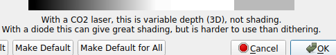
  • Are there factors I have to consider for wood? Can I not use ply? Im concerned about this because I want to make coasters that will be made using 5mm ply. So far as I understand, 5mm birch doesn’t really exist. And 5mm poplar or other hard wood is extremely expensive. If I were trying to do 3D Grayscale, I can definitely appreciate how Plywood layers may affect the results, but Im just trying to get a very superficial result.
  • Is there a cleaning technique? I don’t know how it works, but in any video I’ve seen that show final results, dark shades seem to actually show up as darker shades on the wood. Not just orange/chard, but scortched/black or gray. As I said before… I can kind of get close to this, but even in these rare instances, as soon as I clean the soot off with peroxide, shading is gone.
  • Is Overscan a factor in this? I want to play with Overscan Settings, but I can’t even find the option anywhere, and information about this online seems a bit ambiguous/vague. In Lightburns Lesson series video “#3 - Cut Settings”, Image layers have an Overscanning option that you can enable, but I don’t seem to have this option. Thought maybe it was limited to fill/engraving, but I don’t even see the option there either.

If anyone can help, it’d be deeply deeply appreciated.
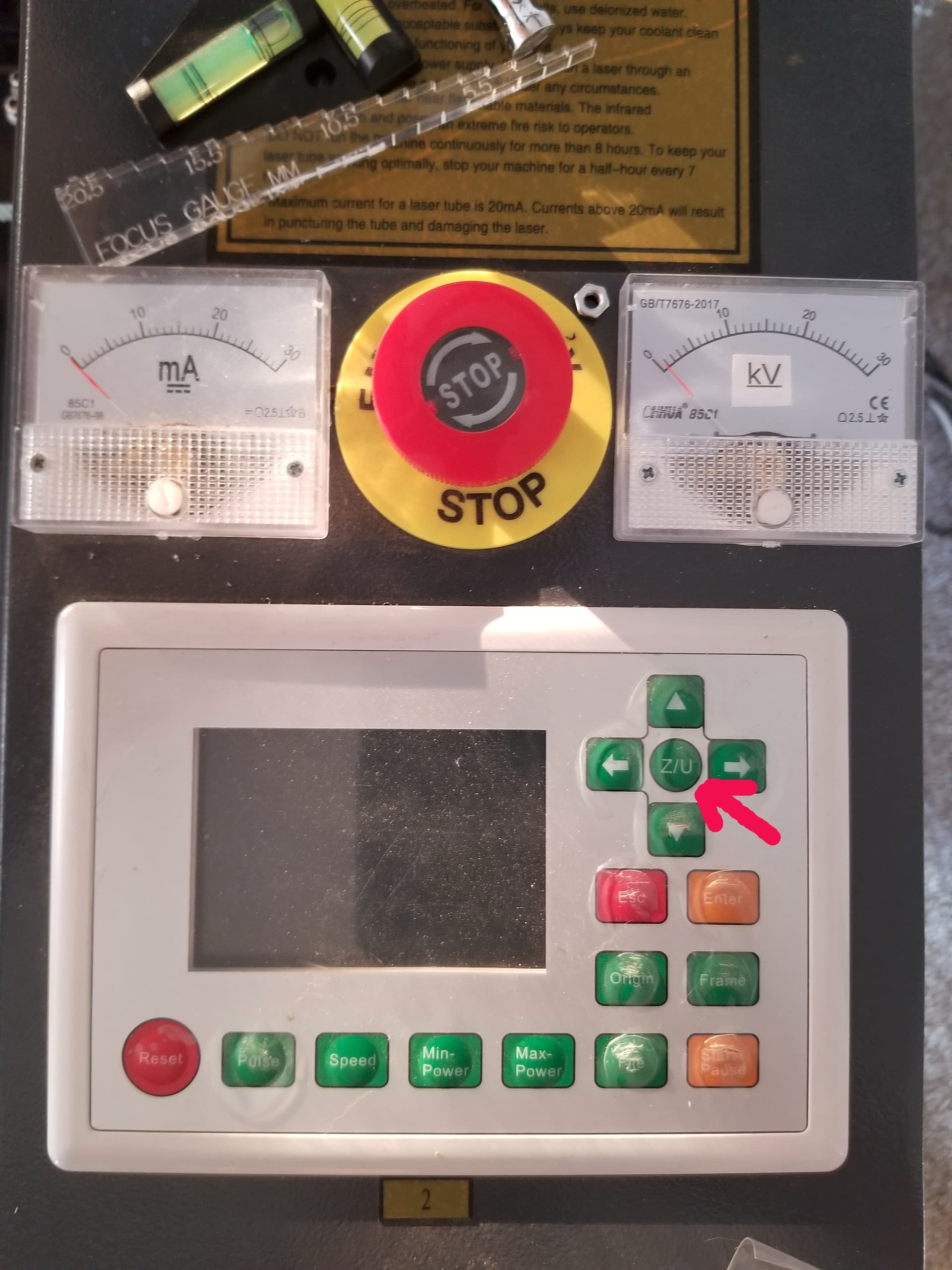
I have an Aeon Mira 7 - 60w.

Appreciate the prior research and the thorough write-up.

Can you provide sample photos of what you’re seeing and if you’re willing the .lbrn file for review.

Certainly but nothing that would explain what you’re describing.

Again, there are various pre-treating methods but nothing that would affect the burn in the way you are describing.

It can be a factor in burning but that’s talking more about refining the quality of the image, not in getting a remotely workable burn.

This option doesn’t apply for Ruida controllers which is why you’re probably not seeing it.

You have a dsp controller, they handle that internally, so no option.

It will give you the infamous ‘slop error’ when you try to run it if it goes out of bounds.

When you select grayscale this warning appears on the bottom of the cut editor.

Screenshot from 2022-03-15 11-34-37

I think you are not in the proper mode you may have to go with some type of dither. Grayscale is really tough with a c02 machine.

Do you have a mA meter, so we have some idea of ‘hard’ you are running. You shouldn’t be burning up stuff at 15%. I engrave plywood at 150mm/s @ 13/9.8 with my 50 watt… Measures 44, but it’s Chinese…

Every material will have ‘better’ ways of doing it, but in general if it’s set right, you won’t have much debris… Do you have air assist? That helps tremendously.

Every type of material varies.

I do a lot with plywood. Engraving/cutting can vary depending on how it’s manufactured. I built a few items and ran out of plywood near the end.

I purchased the same stuff from the same outlet, and some of the parts failed to mate. It was a different ‘batch’ of plywood from the same manufacturer. I was close, but had to test the new material.

There is cast and extruded acrylic and the list goes on… humidity and temperature are another variable. I also found the my ‘tube’ temperature effects current & voltage with the same settings…


Good luck…

:smile_cat:

1 Like

Sorry for the wait, and thank you for your help. I’m going to attach a link to the folder of different results. I’m ashamed to say that I do not have the settings used for each test result leading up to those shown in Image 016. I did however do some more… controlled tests, and saved the settings to those. The image used is part of a gag gift coaster based off real coasters I designed. As such, I don’t really want to post the project file since it’s based of of actual coasters I designed for my shop. I am determined to use the specific image in question due to the fact that it’s giving me so much trouble. I figure if I understand the problem with this image (Randy Tegridy), future images might be a bit easier. But maybe that’s not how this works. The Image Adjustment Settings Im using
I think my most optimistic options are

As you can see, the photo engraving is actually engraving into the wood. Another thing that I noticed is that with any test where the scan angle is 10+ (all attached images/test were done with Scan angle of 10), the right half, or at least bottom right quarter of the bring is being etched significantly more than the rest of the brim/outer-ring. There is lighter colored sky between Rand and the logs hes leaning on, and his jacket is lighter then the logs. If it were the darker more saturated logs, it’d make more sense… but Im curious why it’s happening with the lighter areas in this section of the engraving. Honestly, I don’t know what expectations should be. Im under the impression that when you do photoengraving, I can get a photo/image to be etched onto the wood where it’s still smooth to the touch, without any real texture or depth, but it is still vibrant. Are these unrealistic expectations?

I really appreciate that. I honestly don’t know what an mA reader is… though I imagine its much like an mAh reader for electricity. How would it work for the Laser Cutter.
I definitely feel like using the grayscale what producing the worst issues, so I m staying clear of that for now. I figure Greyscale is probably best with solid wood, whether that be birch, poplar, uh… other wood, and not so much on ply. MDF probably wouldn’t have good results for Greyscale though either huh?
What is vector engraving? I remember coming across it in the Lesson series, but don’t remember. Does it have to do with photoengraving?
I do have air assit on. I have an Ultra-Quiet 2g compressor from California Tools connected, with a moisture extractor in between.

Most of us have the low cost China type machines, yours looks very nice, although also Chinese.


My machine was far from ‘setup’ as far as 50% power really being 50% power. I knew this because I measured the current on the cathode (negative or ground) side of the tube to ground.

I set my power supply to produce 11mA at 50% power level. I can use 85% power and between 18mA and 17mA, which is a comfortable cut power.

My tubes limit is 21mA and I could exceed that easily. It requires you to modify or add some circuitry. It’s pretty simple for most… depends on your skill level.


This is my console, with mA on the left and high voltage on the right. Only the mA is used by most people.


I think you need to lower the power or get more of an idea of the damage you are doing to the material.

If you run 299 dpi you must be able to produce a ‘dot’ that is 0.085mm or smaller. If the ‘dot’ is larger than that the scan it will ‘cover’ some of the previous scan… That is the max distance between the scans.

I can’t speak for others but I can’t really do fine work with any of the stock lenses. I can consistently do 0.10 dots, maybe smaller with my compound lens.

Even if you can make a ‘dot’ from you laser that size, you have to take into consideration how the material reacts.

All of these material ‘damage’ differently. To ‘dot’ acrylic is easy and low power, to ‘dot’ slate leaves a different type of damage…

Wood is one of the hardest to deal with as it can change across part of the same piece. Also what makes it so beautiful…

I generally am happy with 128dpi for wood which is less than 1/2 your current resolution…

None of these are hard and fast ‘rules’ that must be obeyed. Sometimes you need to engrave ‘out of focus’ for the ‘proper’ effect…


Here’s a Russ Sadler file dotSize.lbrn2 that contains some 0.10mm dot patterns. When you load it into lightburn use the zoom-to-selection ‘zoom to selection’ tool, as it’s quite small…

Helps you determine what you can do…

Good luck

Take care…

:smile_cat:

I haven’t had a chance to review your last post in detail but one thing that stuck out to me is that you have minimum power set the same as maximum. I suspect this is preventing the controller from reducing power at acceleration/deceleration in order to avoid burning.

Can you try reducing minimum power and see how that goes?

He’s not using vector, it’s an image, so the min/max shouldn’t have any effect.

I wonder what the reason is for a change in scan angle…

@varxtis I like and use ‘stucki’

:smile_cat:

Thank you! I wish I has a response that conveyed forethought… but unfortunately I haven’t put much consideration behind the difference of Max vs Min power. Sadly, I don’t even adjust these for my regular cutting and engraving unless I see noticeable scorching along any edges. Its horrible, I know. To be fair to myself though, Ive only been using it for about a month. If you’d like to share any experience and clarification on proper adjustments, I love to learn :slight_smile:

I don’t really know the purpose of changing scan angle is either, but whatever it is, setting it to 0 actually helped a bit. I’ll probably be purchasing 4" and 1.5" lens in the next week or so. Though, I have a feeling it has to do with settings and power levels. I don’t really know how to confirm or measure the kerf Im getting, but I can get some very fine detail. I downloaded the file you linked and will run it later this evening.

I did a whole slew of new tests, making sure to record the settings along the way. I tried stucki and man did that help things. The results were great. I managed to narrow it down to 50pwr at 200dpi. Thank you for the suggestion. Also, I still don’t know what the reason for angled scan is for, but this image shows two runs with the exact same settings, except the bottom one is at 20 degree scan angle. It really burned in to it. This is a better view of the depth.

Is it possible your focus beam is not a dot and rather elliptical along roughly 20 degree angle? Have you done an alignment check?

@_@ Ellipse? I didn’t know that could be a thing. I’ll contact Aeon and see.
About a week and a half ago I ran through a mirror alignment as well as red dot alignment. I double checked this morning and it seemed to still seems fine.

These apply when the ‘head’ is changing speed and the laser is still firing, only during vector cutting/engraving.

When you run a ‘scan’ or fill operation and you set the speed, like 300mm/s, the head uses ‘overscan’, or an area outside of the image area so it can attain the 300mm/s you requested.

This is computed within the DSP controller. No user options here…

At some point, if you haven’t already, you will attempt to run an image and the controller will complain of a ‘slop’ error. This means the overscan is going out of the work area. Slow the head or move the engraving more to the center to allow the head more area to slow down, change direction and speed back up.

With a vector image, for example a square. The laser must be on through the whole operation, so the head is slowing (not moving 300mm/s) so it can stop to go around the corner, the laser must be ‘on’.

It handles this by varying the power between min/max relative to the speed of the head.

This is a graph I made from my experience with min/max and speed. Maybe it will help…

The jump-off speed is set within the controller for each axes. When you move the head <= to the jump off speed you will get only minimum layer power.

This can also be affected by the console settings, where it’s possible to override some of these by the operator.

Hope this helps with the min/max.


We all been in the new user state and when through that,

10 years from now you will probably have many questions that haven’t been answered… Such is life and don’t worry about posting here, as we all learn…

You may have been told, like me it’s a steep learning curve… I found it more like climbing up an overhang… :crazy_face:

I think you should lower your power, it’s pretty scorched… Did you want the 3d type of engraving?

Here are some examples of actual failure modes you see in the beam.

The best place to check your beam is at the tube or mirror 1 (m1).


To shorten the length of a post you can ‘highlight’ the question from someone and click ‘Quote’, this will give the question highlighted.

You can answer multiple questions to different people in one response.


Good luck

:smile_cat:

I’m just going from the symptoms. You’re getting a different burn based on scan angle. That could be from material or something in the engraving process. I didn’t see anything in the material that would contribute to this so suspect something on the engraving. Speed didn’t seem to be the major factor so possibly something with the beam itself. If the beam was somehow biased along that angle It could potentially cause more burning then along a different angle.

Make sure your laser head is vertical to the bed and that the lens is seated flat and perpendicular to the head.

This topic was automatically closed 30 days after the last reply. New replies are no longer allowed.