I’m currently working on a guide for just this, but in the mean-time, this video might be of use:
At a very high level you want to run through these tests in this order:
1. Focus; use the Focus Test tool (Laser Tools>Focus Test) for machines with a controlled Z axis. For those without, use the slanted board method to find the focal length, or use your normal method of focussing. Some people prefer the look of a slightly defocused laser for engraves, I reckon follow this process with a focussed one first, and then change it later if you wish. The following steps will be easier with a focussed laser, for the first time.
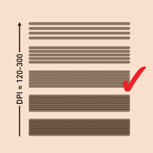
**2. Line Interval/DPI; These settings are tied together. They change the distance between each pass (scan) of the laser head. If this setting is too low, images will be very dark (as the lines overlap). Too high and the image will be too light. Use the Laser Tools>Interval Test to find the point where the lines juuust touch (don’t overlap, nor have gap).

You will need a microscope or strong magnifying glass. You could also do this by engraving some gradients (image below) and varying the line interval in the cut/layer settings, try between 120-300dpi (0.08-0.2mm).

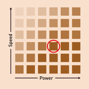
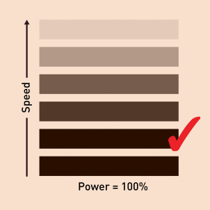
3. Speed & Power; changes depth and darkness of engrave.
For CO2: Use the Laser Tools>Material Test Generator, varying speed and power, find the lowest power and highest speed that it reaches the darkest dark colour.

For Diode: keep power at 100 and just vary speed, find the fastest speed it reaches the darkest dark. It’s a good idea when performing these tests to make your test-boxes as wide as your final image as speed/acceleration has a lot of effect on the darkness of an engrave.

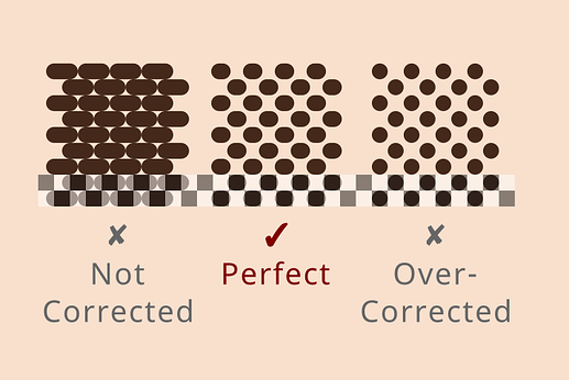
6. Dot correction; Beams have thickness which often makes dots longer than they should be, we can correct this with dot correction (in layer settings). To test it, engrave a 50% gray rectangle, in ordered image mode with bidirectional scanning turned off.

You are looking to achieve a checkerboard pattern that is 50% engraved and 50% not.
7. Image mode and Scanning Direction: Your layer settings are nearly complete. Ordered image (dithering) mode is great for the last test, but makes for choppy looking engraves, so switch it back to another mode, such as Jarvis.
Uni-directional scanning makes it much easier to see the pattern in lasers that haven’t had their scanning offset adjusted, but it takes a lot more time than bi directional, so switch bidirectional back on.
Ordered Image Mode:

Jarvis Dithering Mode:

8. Image Adjustment (per image); After this if you are still not getting the look you desire, it’s because the image you are using needs some adjusting, which you can do using the Image Adjustment tool. Try changing the brightness, contrast, and Gamma, along with the enhance features.
Hope this helps!

