The Lightburn Camera Mount (purchased or 3D printed) pivots or swivels longitudinally.
After (or before) calibrating the camera, how does one get the “pivot” of the Lightburn camera (in the mount) to be perpendicular to the cutting surface workspace?
If it isn’t perpendicular, it distorts.
For example, I have engraved crosshairs on a jig.
If I move the cursor using the “Set laser position” (Alt-L) feature, and place it directly over the center of the crosshairs, it does not move the laser head directly over the center of the crosshairs (so that if I would pulse fire the laser, it does not hit the center of the crosshairs).
In a recent attempt, for example, the laser tube traveled to a position about 40 cm “south” on the Y-axis of the honeycomb from where the “Set laser position” cursor indicated in the Lightburn workspace after having updated the overlay in the Camera Control.
Would it be possible to 1) Update Overlay, 2) Draw a rectangle corresponding to the outside edges of the overlay camera view in the Lightburn workspace, 3) etch that onto a piece of white posterboard on the honeycomb laser surface workspace, 4) divide that into “thirds” – and use the dimension from the “thirds” as the dimension for my calibration pattern size?
It sounds complicated and shouldn’t be necessary. Camera and lens alignment is about calculating and compensating for these variations of disorientation. What I mean is, on my standard 60Watt OMT laser I have a 90 degree LB camera mounted in the lid. Of course I have tried to have it placed in the middle of my work bed, but it still isn’t. Before I calibrate my camera I adjust it in the preview window so that my bed is covered. Here I change the angle of the camera body itself a little, knowing that it is not perpendicular, but it doesn’t matter that much, the calibration compensates for those errors.
What is crucial in my experience is that the actual location/angle and distance of the camera does not change after calibration. A single degree or millimeter ruins the result and the deviation error of the camera becomes too large.
I may have missed the “preview” window and didn’t know that I could make adjustments there. I have the camera attached to the inside / underside of the laser lid. I actually laser-cutted a mount to use instead of the 3D mount. Thanks for your observations. They will no doubt get me closer to the goal.
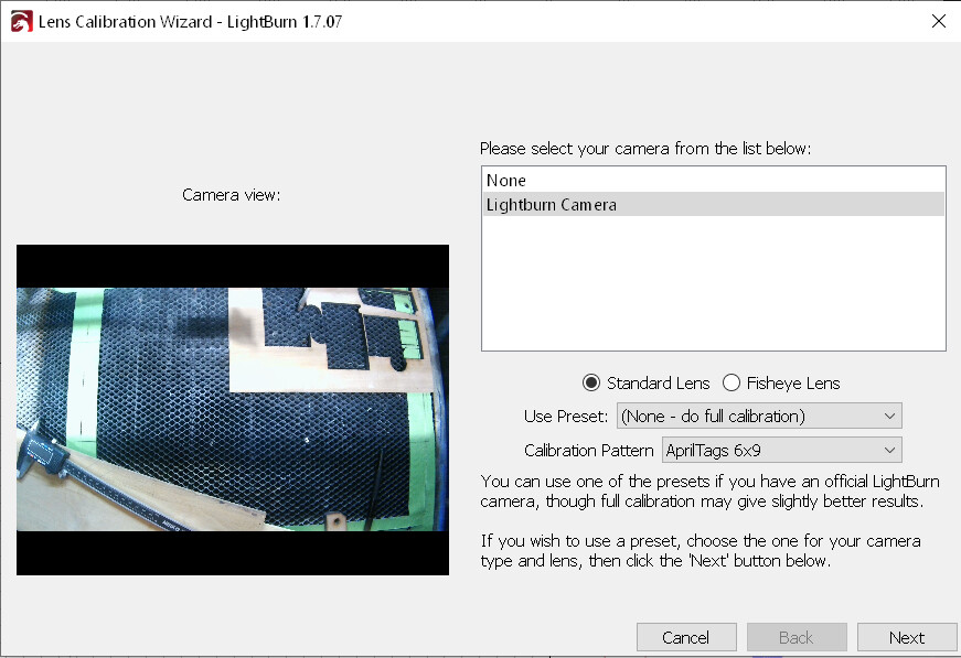
This is the image from Lightburn’s Camera Alignment Wizard. See the curvature of the lines? I don’t think I selected the fisheye option in the Calibrate Camera Lens utility . . . so it suggests to me that the camera is not directed at an exact 90-degree angle with the work surface . . . and accomplishing that, it seems to me, would be tedious with the lid closed.
OR would this “aberration” be “fixed” once I use the alignment procedure, aligning the lens with the targets printed on the work surface? I know that I followed that routine once, but didn’t get the results for which I was looking.
ALSO, is it possible to MANUALLY focus the Lightburn 8mp camera? Again, this seems like it would be difficult to do without trial-and-error since the camera is only properly positioned with the lid closed.
I’ve toyed with the idea of cutting a “lens-sized” hole in the lid of the laser. I can always cut another cast acrylic piece for the lid . . . but I’m not interested in rushing into things.
If it is before calibration then it is “normal” with a curved image. What “irritates” me a bit about your image is that it should be a larger area of your work surface, it will be adjusted later in the process but of course cannot be larger. That is, if it is the max view of your camera, then your mounting height is not high enough.
As long as you have your entire work bed covered, no matter how distorted it looks, it will be adjusted during the calibration process. As I said, my camera is not placed 100% in the center either, but I have approx. 5cm of coverage beyond the machine bed. On a daily basis I have a deviation across the machine bed of approx. 1-1.5 mm, but with a little fine-tuning, if I need precise placement of letters on a pin for example, then I’m at sub mm level.
Remember to put the height of your test piece into the chart, and when you print/engrave the 5 target discs at the end, you may not move them, they can’t (usually) be reused either.
(On my diode laser machine I have also drilled a hole in the box, but I will not do that on my OMT CO2 laser.)