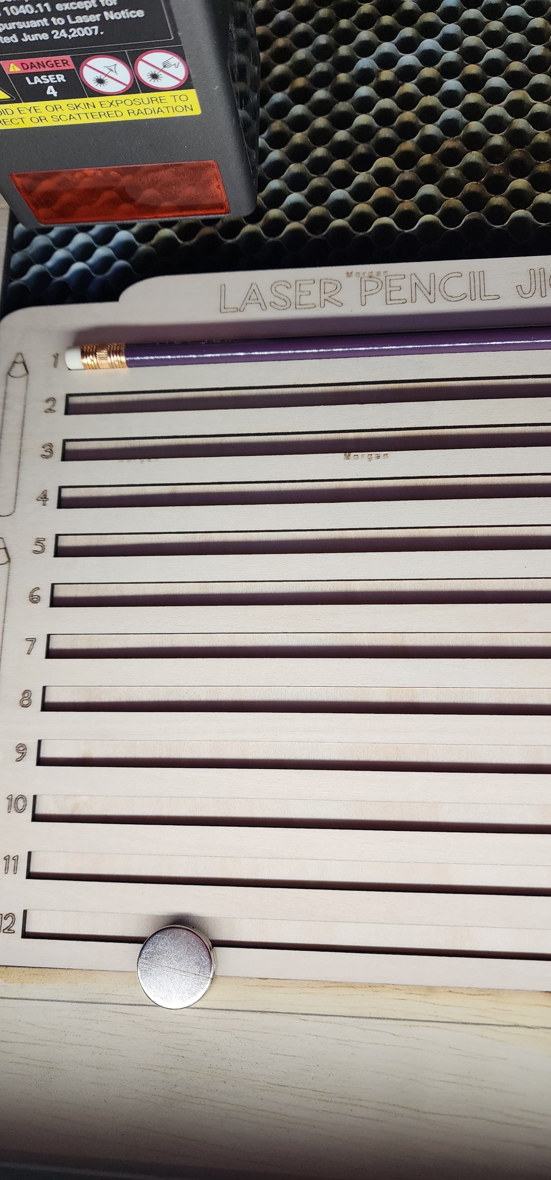
I am using a jig to help ensure position of engrave. I have an “XY home hack” in my laser bed to also help with correct position. I gave up using camera, as it never aligns with engrave. I have what I want centered in my jig space on LB, but when it engraves, it is off. Isn’t the jig supposed to ensure position? Included is video of issue. Can’t upload video. Pics included. Engraves at top of item, not center

There’s a bit more to it than that.
Things to verify:
-
Does the machine home reliably every time it’s turned on? Put some cardboard on the platform, turn the machine off, move the laser head to the middle of the platform, turn it on, let it home, then without moving anything pulse the laser. Repeat that five times: if five shots go into one tiny hole, it homes well enough.
-
Are you using
Start From: Absolute Coordinatesmode? If so, then the LightBurn workspace maps exactly to the physical platform, as determined by the home position. If you’re usingCurrent PositionorUser Origin, then you must set the position correctly. See the doc for the details. -
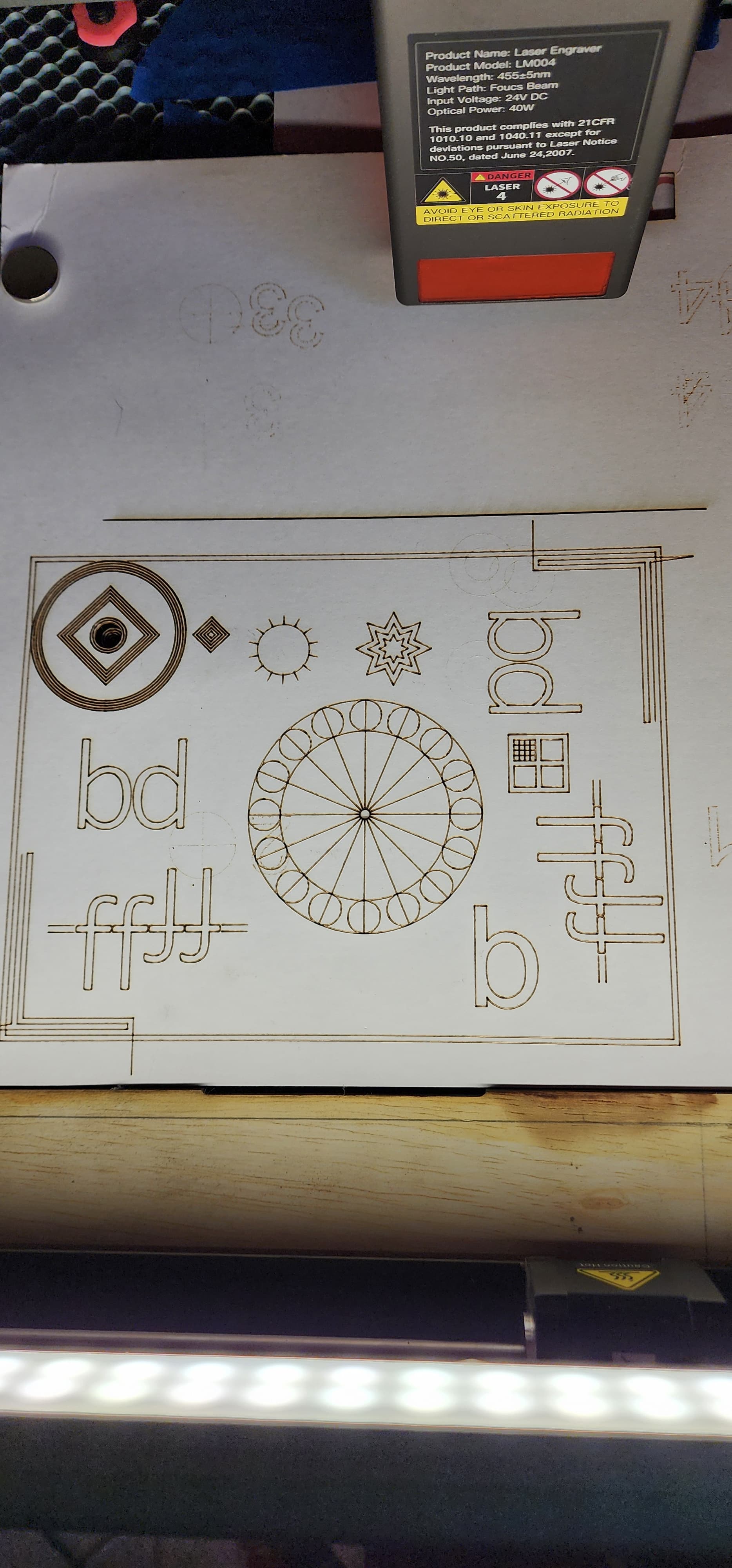
Is the machine mechanically accurate? Uniformly scale this test pattern to fit the platform and run it as fast as it will go in Line mode with optimizations turned off and power set to mark a sheet of cardboard. Any differences from the design will be informative:
Run it five times on the same sheet of cardboard, turning the machine off each time. If it looks like a single run after all five, then the machine is stable and accurate.
- Is the fixture & honeycomb at the same location every time you run the job? Add a target to the template and burn it into the fixture. Whenever you set up the fixture & load the template file, use
Position Laserto move the head to that target on the template, pulse the laser, and verify the hole lines up with the target on the fixture. Better yet: two targets in opposite corners will verify alignment.
If all of those checks work as described and it still doesn’t line up, then something … interesting … is going on.
2 Likes
Yes, that is what it is for, BUT…
Do everything @ednisley said to ensure it is not a mechanical issue.
- Is the laser frame fixed so it cannot move?
- Is the honeycomb fixed so it cannot move?
- Was the same template you used to cut the pencil holder slots used to add the text?
- Did you use he Array Tool to add the text?
- Is the pencil fixture or honeycomb keyed so the fixture goes in the same exact place tomorrow?
My machines were anchored, I just Friday aligned and anchored the honeycombs. I ensured the beam was exactly in the corner of the honeycomb when Homed. My fixtures (I have about a dozen) all fit in the 0,0 corner accurately. I did this for two machines.
When I fire the laser at 0.0, it burns the corner tip of the board or fixture. So I know what you need can be done. Just do not try rushing the tooling setup.
Thank you. I will try this tomorrow. It seems to home accurately when turned on and I do have absolute coordinates. I’ll try the tests and see…
Use “current position” and not absolute coordinates. Make sure you have a defined position on the jig you can set the laser on (like bottom-left corner of the jig) then you can move the laser head to this position and start from there.
I described some methods here: Coordinate systems & workpiece alignment - Diode Laser Wiki
1 Like
With two targets you can use `Print and Cut’ to correct for both alignment and rotation errors. ![]()
I don’t know about the rest of the people here, but I have no idea what this hack is or if it’s operational. Might be nice if you can link to it or explain what you did.
Most of these work on the coordinate system based on quadrants. The center of you workspace is generally not the best choice. I understand why you do this, but it may be part of the problem with your alignment.
The key with jigs is to ensure they are attached some way to ensure the machine coordinates can be reproduced in the same spot. I think you should be able to use any of the start from values if you understand the coordinate system.
I use absolute coordinates to create the jig, but commonly put a user origin as to where the corner of the material is located. I can then enter those values, move the head, press origin on the machines console and set start from to user origin.

We probably need to know more about how you set it up and expect it to work along with what hack are you using?
To make this work, you need to be able to position the jig in the machine in a repeatable manner if you want the machine to handle this.
If you want the software to handle it, you need to use one of the other tools for aligning the image with a camera.
![]()
1 Like
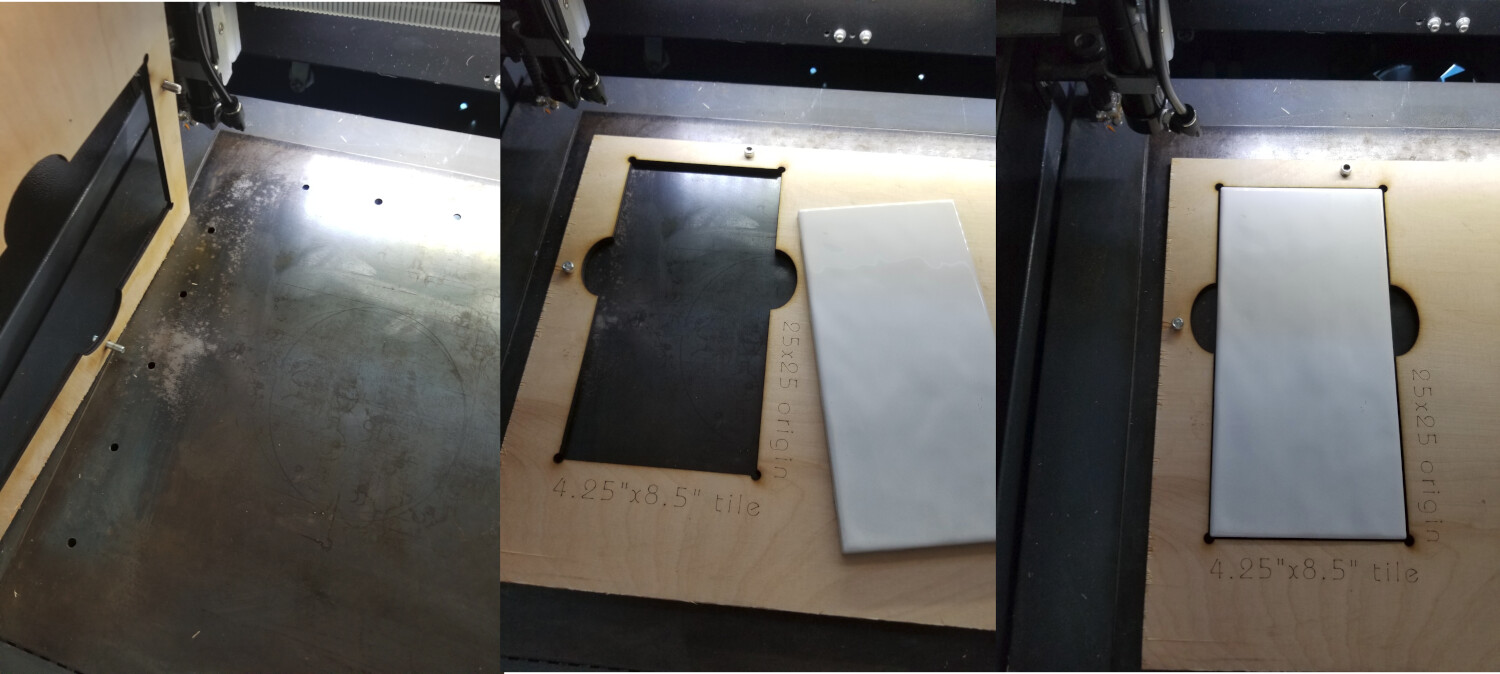
The XY hack allows me to place material in the corner of my workspace in the same spot. Where the laser actually starts firing. Here is a better explanation at minute 14

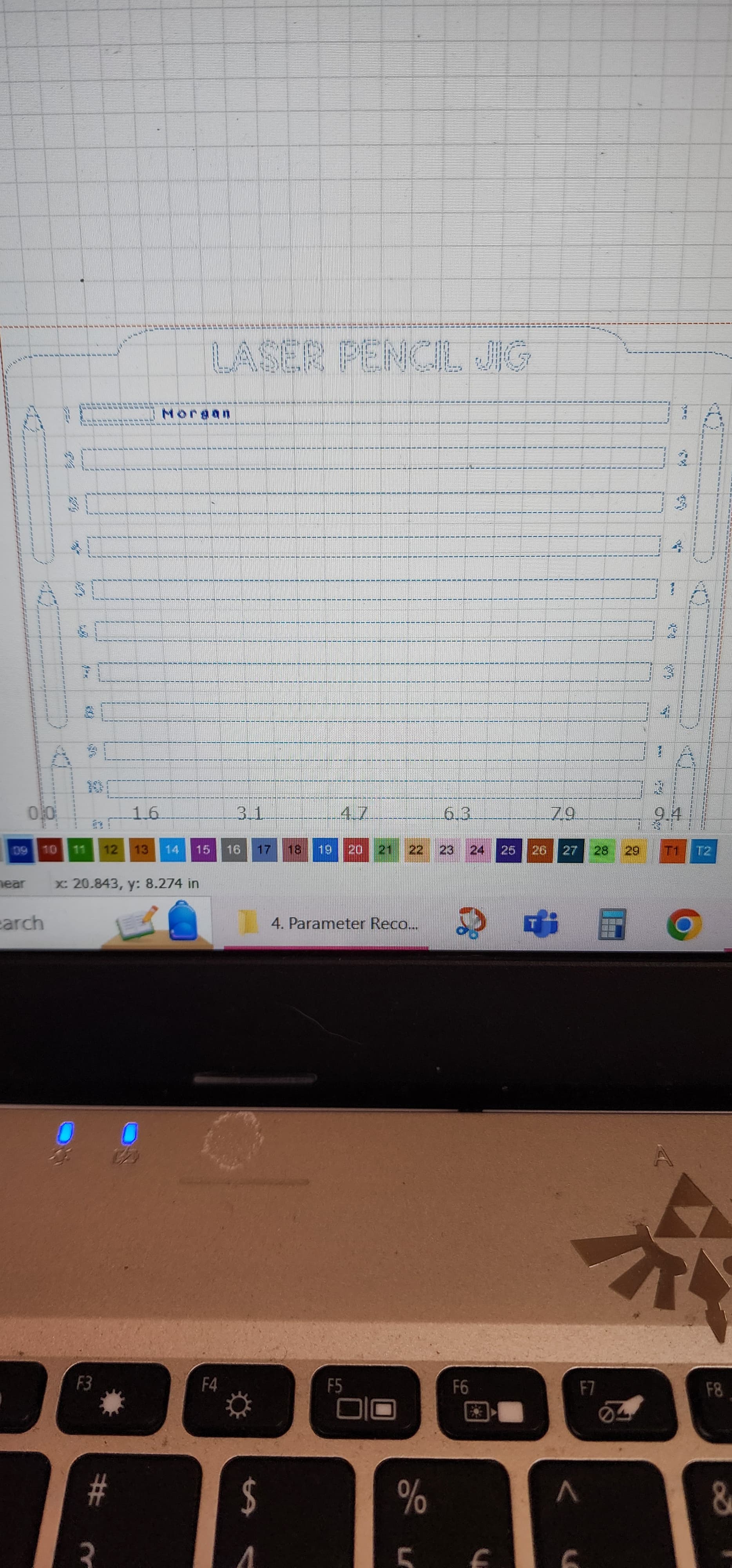
When I say I have it centered, not in my workspace it’s centered on the jig, where it would engrave. That’s the first picture. My jumig is situated in the lower left corner
1 Like
I need to research print and cut. I have seen it, don’t know how to use it. Thank you


Have fun
![]()
1 Like
My whole long-winded checkout process is intended to verify the machine will cut at the same place every time, so all the positioning stuff Goes Away.
When you cut the fixture from the template at a specific spot using Absolute Coordinates, the machine will always cut at that specific spot forevermore, so as long as the fixture never moves (a good fixture will always be at the same position), then you won’t need to screw around with any manual positioning.
You’ve seen plenty of ways to get you where you want to go, but most of the paths depend on having a stable & accurate machine. Without that, it gets a lot harder to predict what’s going to happen each time.
2 Likes
I did everything. When I performed all the tests everything lined up, the test run looked as if it was one path after 5. But I tried print & cut and it was way off. Not sure why. I will try lining up again and see if it works.
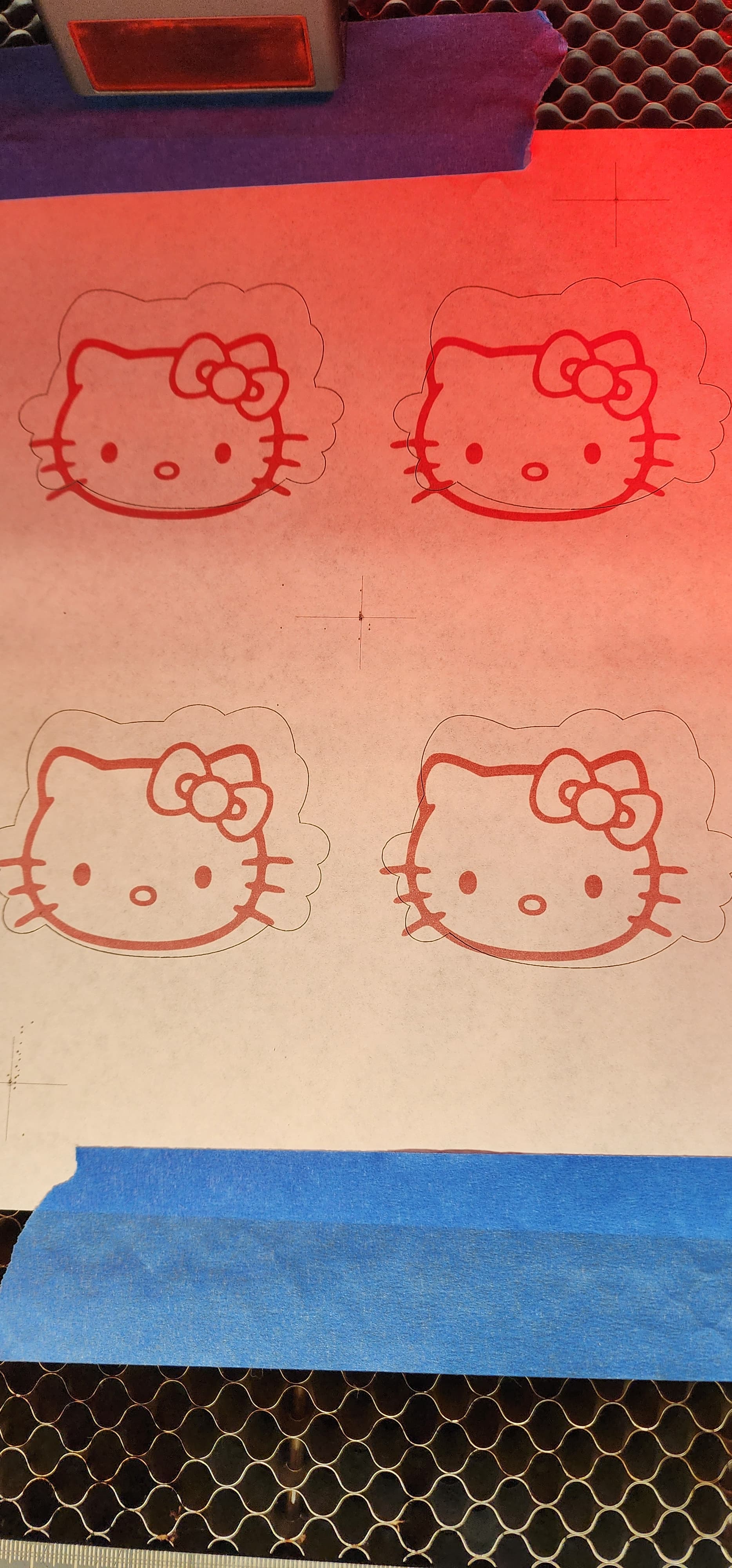
Are the Hello Kitty images printed on a piece of paper stuck to a sheet of something to be cut out?
If so, what do the targets look like in the LightBurn workspace and on the printed material? Did you create the LightBurn template from the original digital artwork as the printed sheet, a scanned version, or something else?
Screenshots of the LightBurn layouts and photos of the printed sheet will let us see what you see.