Positioning Issue

Summary: When etching a simple object, such as a crosshair, it is not etched at the same location
(XCS etches the same object repeatedly at the same location)

Configuration:
Laser Engraver: Xtool D1 Pro (latest Firmware V40.31.006.31 B2)
Lightburn version: 1.4.03
OS: Windows 10

Reproduction:

  1. Draw two perpendicular lines to create a crosshair
  2. Set the X and Y coordinates i.e. 100, 100 (Absolute Coordinates is used for positioning)
  3. Click on the Home button
  4. Click on the Start button: The crosshair is etched at the right position
  5. Click on the Start, to etch again: The Y position seems to be off
  6. Click on Start, to etch again: The Y position seems to be off (again)

It does not always etch with a different Y value, but very often. Also, the distance between two Y values is not a constant; the distance is small but few mm

Am I doing anything wrong?

Please let me know if any questions.

Thanks

1 Like

I would make sure my set screws are tight on the drive pulleys.

Thanks for the suggestion.

As explained, XCS does it properly. It is highly likely, that it’s a software issue???

Also, if it helps: The location where LightBurn etches during the first iteration is “always” where XCS repeatedly etches.

1 Like

This is very interesting. I haven’t used XCS so I will need your assistance to confirm some settings.

Small Y-Axis travel errors can be created by Lost Motion. Lost motion is like a car spinning its tires. The motion is counted by the instrumentation but the actual travel distance is lost.

There are a couple of ideas leading me in this direction.

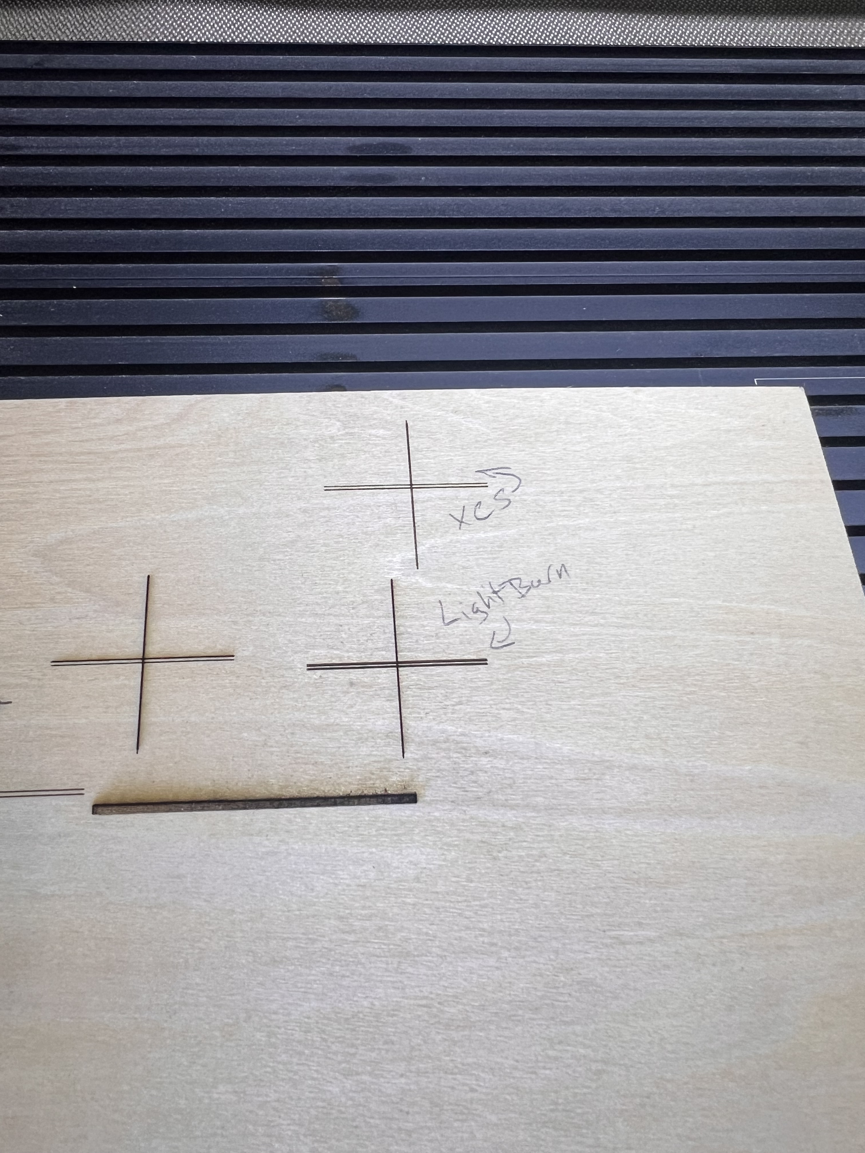
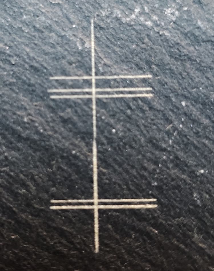
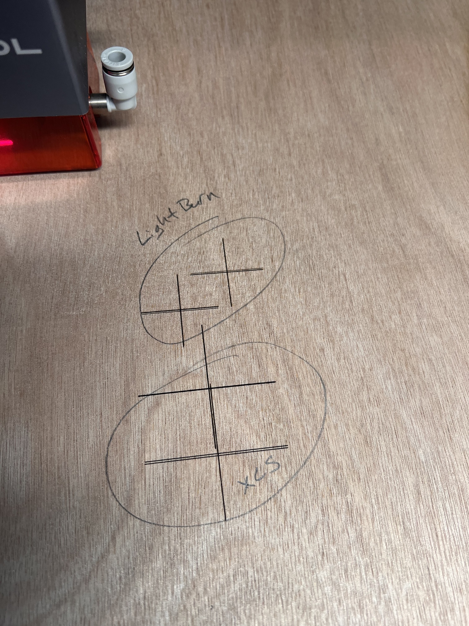
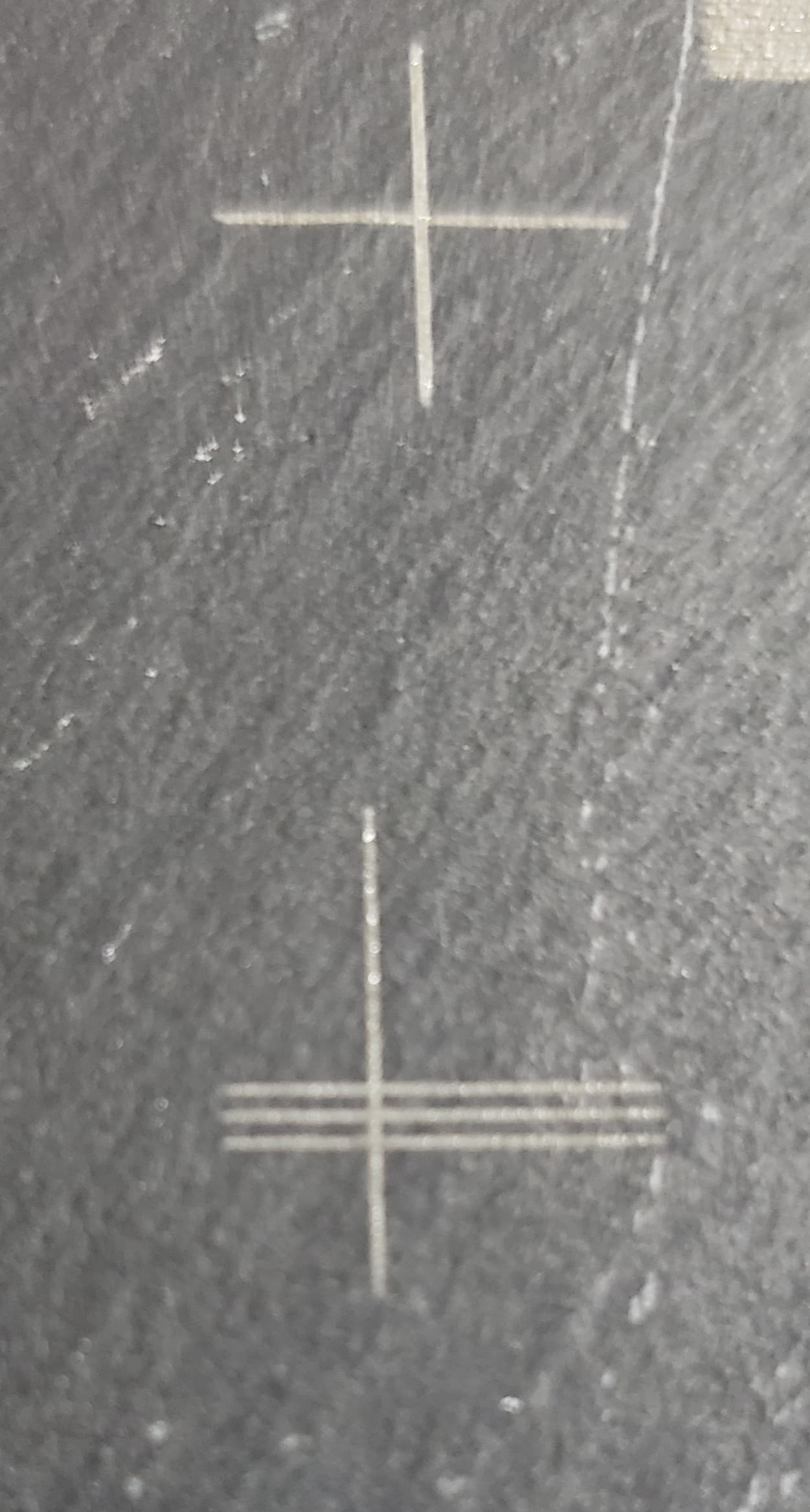
  • The variation is a few mm and it is in the Y-direction only.

The engraver moves more parts (more mass and weight) when it moves in the Y-direction because the whole gantry has to move. Moving in the X-direction can be successful with higher accelerations because there’s less mass to move. Force = mass * acceleration

F = m * a Force is what causes the toothed belt to move or skip.

  • The GRBL controller counts every step.

The error isn’t reproduced perfectly / identically each time. The variation is outside the counted part. This leads us solidly to a mechanical variation.

An acceleration setting that’s very slightly over what would be perfectly repeatable is the idea I’m leaning toward.

I’d like to explore the speed and acceleration settings in LightBurn and XCS to confirm that they’re identical.

In the Console window in LightBurn please type the following:
$$
then press Enter.

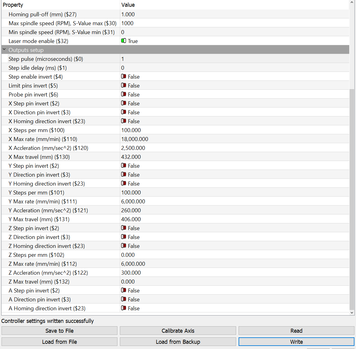
Please select and copy the text in that report from $100 until the end of that report and paste it into a reply here.

Because we only need a few numbers, a screen capture isn’t too bad.
Your numbers will be different than mine. That’s fine. :slight_smile:

2023-11-13 console output 116590

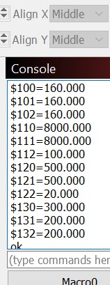
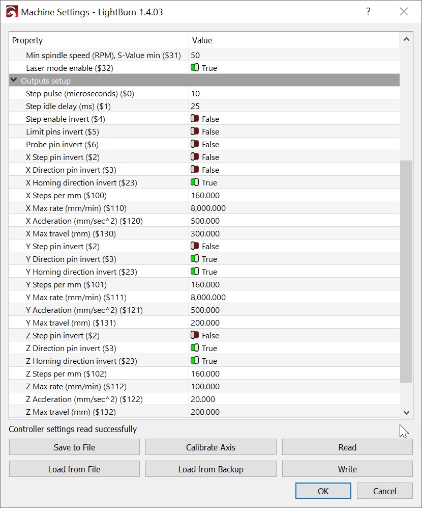
These numbers are also in Machine Settings. To access them click Edit, then Machine Settings then click the > symbol in the last line next to Outputs setup. Skip the dire warning. :slight_smile:


Click to expand Image

Note here that the Units are shown. Knowing the Units applied to acceleration (mm/sec^2) and speed (mm/min) is critical for comparing them.

In XCS, find the machine settings that relate to speed and acceleration.
Please screen capture and share that Image here. You should be able to drag and drop it from your desktop into the reply window where you type your response.

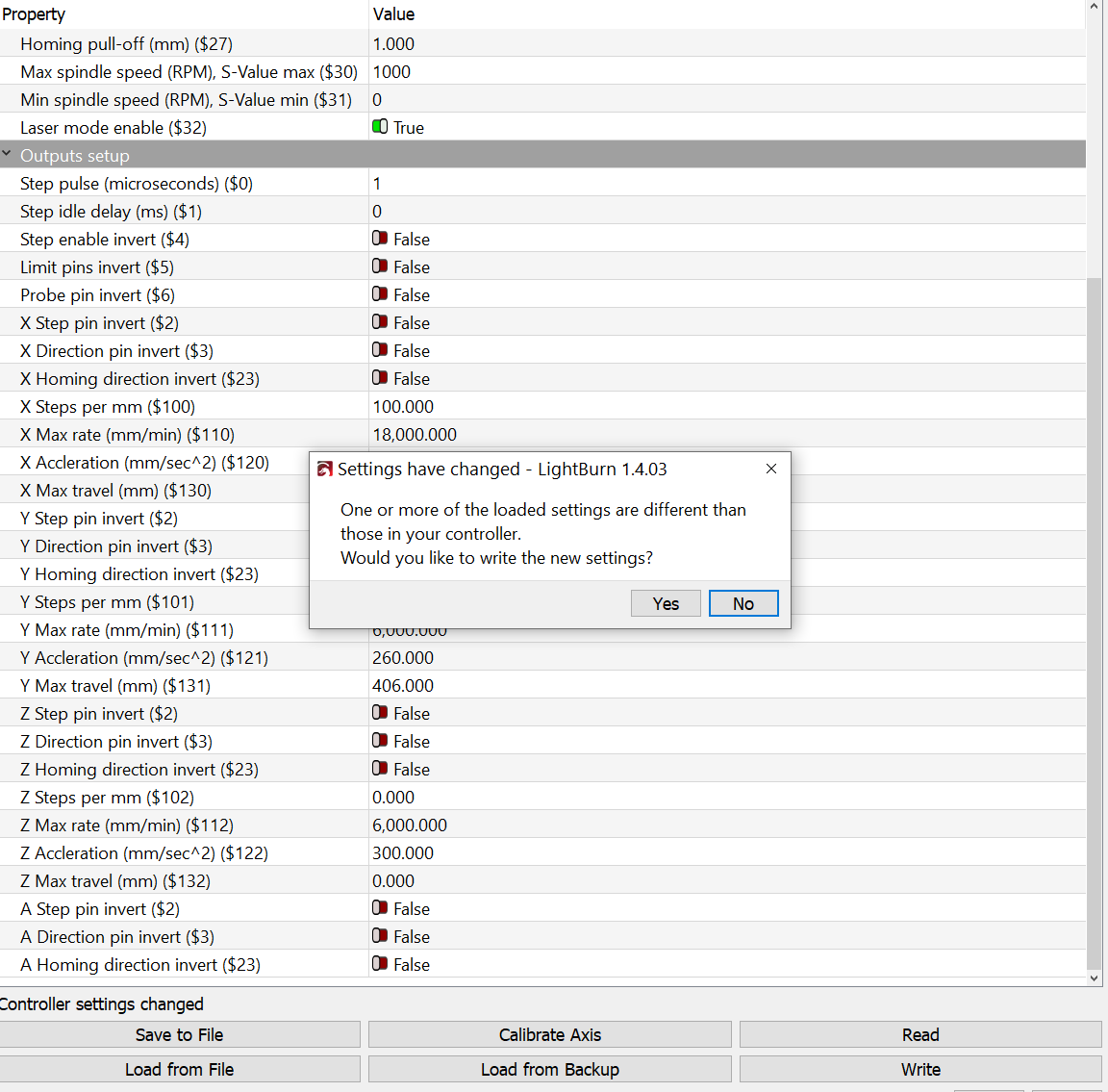
If the settings are different, you can adjust the settings in LightBurn to match.
If the settings are identical (speed, acceleration, and their units) we’ll test the Y acceleration settings to see if an increase makes the error larger and a decrease makes the error vanish.

Thank You for the detailed explanation.

Below are the requested
1. The output of the “$$” command:
(Just in case, I am sharing the entire output)
$$
$0=1
$1=0.03
$2=0
$3=0
$4=0
$5=0
$6=0
$10=255
$11=0.0
$12=0.0
$13=0
$20=0
$21=1
$22=1
$23=0
$24=25.0
$25=3000.0
$26=250
$27=1.0
$30=1000
$31=0.1
$32=1
$100=100
$101=100
$102=0
$110=18000
$111=6000
$112=6000
$120=2500.000000
$121=300.000000
$122=300
$130=432.000
$131=406
$132=0
ok
ok

2. The Machine Settings in LightBurn
I am attaching the JSON file
Lightburn Settings - v2.lbrn2.lbset (5.4 KB)

3. The Machine Settings in XCS
I could not find any such info in the machine settings section, I am attaching the file that I have used to configure both XCS and LightBurn
xTool-D1ProV3.lbdev (3.9 KB)

I don’t know if the LightBurn setting
{
** “Desc”: “Y Accleration (mm/sec^2) ($121)”,**
** “ID”: “0x79”,**
** “Value”: 300**
** },**
Corresponds to the XCS setting???
“Sim_MaxAccelY”: 300,

I hope that the above will help.

the LBDev and lbset files would both have Lightburn speeds and accelerations in them. I will verify right away.

I’ll still need a screen capture from XCS to confirm and compare.

GRBL was an open source project. The meanings and definitions of the project are all still available here: grbl/doc/markdown/settings.md at master ¡ gnea/grbl ¡ GitHub

in LightBurn:
$100=100 x-axis steps per mm
$101=100 y-axis steps per mm
$102=0 z-axis steps per mm
$110=18000 x-axis Max travel rate (speed) mm/min
$111=6000 y-axis Max Travel rate mm/min
$112=6000 z-axis Max Travel rate mm/min
$120=2500.000000 x-axis acceleration (mm/sec^2)
$121=300.000000 y-axis acceleration (mm/sec^2)
$122=300 z-axis acceleration (mm/sec^2)
$130=432.000 x axis length
$131=406 y axis Length
$132=0 z axis Length

These match the values in the lbset file,
the Machine settings don’t appear in the LBdev file.
What does appear in the LBdev file are the simulation settings but they’re lower than what we see above. These aren’t necessarily close to what’s in the engraver.

"Sim_FastWhiteScan": false,
"Sim_FastWhiteScanSpeed": 0,
"Sim_GlobalFactor": 1,
"Sim_MaxAccelX": 3000, NOTE:  $120=2500.000000  (above)
"Sim_MaxAccelY": 300,  NOTE:  $121=300.000000 
"Sim_MaxSpeedX": 500,  NOTE:  $110=18000 mm/min (or 300mm/second)
"Sim_MaxSpeedY": 400,  NOTE:  $111= 6000 mm/min (or 100mm/second)
"Sim_MinCornerSpeed": 1,
"Sim_RapidSpeed": 100, 
"Sim_ScanAccelX":

Yes, it would have helped, but I’m not sure if such a screen exists. XCS does not seem to expose those settings. I would gladly share the Screen Capture, if you know where that screen is. The Machine Settings do not include such details/settings.

I can try to contact the Xtool Support Team.

In any case, XCS seems to position itself properly and consistently

I found some of their settings inside their firmware.
From: D1S_app_V40.31.006.01B2_20230206.bin

$100=100
$101=100
$102=0
$110=18000
$111=6000
$112=6000
$120=%f
$121=%f
$122=300
$130=432.000
$131=406
$132=0

Yes, I’d love to know why. I might keep picking at this.

With your xTool D1 pro connected to LightBurn, please enter the following into the Console window:
$121=260
then press enter.

Please verify that the setting changed by requesting the machine settings $$ report, as you did above.

With the reduced acceleration along the Y axis you should have more consistent results in LightBurn. Please let me know if this fully corrects the unwanted behavior or not.

Thanks!

The command $121=260
Is not changing the value of $121. (Just in case, I have restarted LightBurn after issuing the command, I have issued the command multiple times, and the value is still 300)

Should I try to change the value in Machine Settings?

Also, I have contacted the Xtool Support Team, asking if it is possible to view/export those settings, and/or issue “$” commands.

Thanks.

Recently, I was told that the xTool controller doesn’t store position to the same extent that grbl controllers do. You may have success selecting ‘Current Position’ in LightBurn to address this particular positioning concern. Again, you’d have to test this to confirm. We have not confirmed the cause of the lost motion.

Yes, Please do… and Please test the Write button at the bottom of the Machine settings window to write the change out to the controller.

The Persistence of Machine Settings is most often a chosen setting that is deeper than the regular machine settings. Usually, it’s something called a build-time setting. It’s made in the firmware in the controller by the folks that ‘do the build’ or Compile and Flash the firmware. I don’t know of a way to re-open the persistence of Machine Settings after they have been closed. They may have built another way.

GRBL (or grbl) was originally an open-source GCode motion planner.
GitHub - gnea/grbl: An open source, embedded, high performance g-code-parser and CNC milling controller written in optimized C that will run on a straight Arduino

Most Laser Diode engravers are built on more advanced open-source versions of this.
GRBL-HAL https://www.grbl.org/what-is-grblhal

GRBL_ESP32 https://github.com/bdring/Grbl_Esp32

Part of the open-source License agreement can be an obligation to release your version of the open-source code so that others can learn, tinker, and enjoy. With source code, you can ‘roll-your-own’ custom firmware build with any or all of the build settings or machine settings set the way you want to set them.

Some manufacturers are reluctant to share their customizations. Many are under no obligation to do so.

Open-source versions wouldn’t be able to use or access customizations like XCS or XCS project files. It’s a uniquely protected “Creative Space” and it’s worth reading their terms of service. https://www.xtool.com/policies/terms-of-service

If xTool has locked out their settings and their file system then that’s the way they’ve built it. If they don’t allow users to download and share their files, that’s their choice too.

Customers can be quite creative and I look forward to seeing the eventual successes or repercussions of their closed ecosystem.

Unfortunately, it did not work as expected. The changes are written successfully to the file (See snapshot, and I checked the content of the file); however, when I close the Machine Settings window and reopen it, the value is reverted to 300.

I even tried to load from a backup file where the value is set to 260; the read is successful, as shown in the below attached snapshot. Again, the value is reverted to 300 once I close the Machine Settings and reopen.

In both cases, the “$$” command shows $121=300

In this Use Case, Absolute Coordinates is a requirement. I found this behavior when checking if the Absolute Coordinates of a “point” of the Work Area, is the same in both XCS and LightBurn (and they seem to match)
In other words, the below should etch at the same location in both:
1- Goto Home
2- Etch an object located at (x,y)

I agree.

I don’t have one here for testing so I’m somewhat at a loss to reproduce the behavior. I have elevated this to the entirety of the support team to attempt to resolve this.

Someone else might jump in, but I’ll keep my eyes on this as more information comes to light.

A few clarifying questions please:

  1. What are the steps for the equivalent test on the XCS side?
  2. Instead of pushing Start multiple times, if you do multiple passes at the layer level, do you get repeatable crosshair location?
  3. How long are you waiting between Start runs in the LightBurn test?
  4. In LightBurn, can you go to File->Save gcode, save with .txt extension, and upload the file here?
1 Like

Hey guys, I ran this test on my 20w xtool d1 pro with the latest firmware, XCS, and LightBurn 1.4.03 and I am seeing a shift on the Y axis with both software consistently between homing.

Run the cross hair, let the machine home, run again.

My assumption is the repeatability of the Y limit switch is not great based on this and many posts I’ve seen about them.

I’ve seen homing repeatability issues with xTool machines before. But based on the steps listed by OP it doesn’t appear that he is homing in between runs, just re-hitting Start button.

Would be good if OP can confirm.

Many Thanks

I am testing with XCS version 1.6.10-2023-10-08-21-34-45; Absolute Coordinates were introduced in version 1.6.10 (By the way, version 1.6.10 does not compute properly the dimensions of an imported PNG photo; as a workaround, I create an SVG in Inkscape, import the photo and import the SVG in XCS; older versions compute properly the dimensions)

In the below photo, the differences between the top and bottom crosshairs are

  • (Though it automatically returns to Home after etching) In the bottom crosshair, I have added an explicit “Home” between two “Sarts”
  • In the bottom crosshair, the second “Start” did not fail which explains that there are only two horizontal lines

Homing is done automatically, and as shown in the picture above, it does not seem to impact on the behavior.
I have omitted the superfluous steps in the reproduction.

The same steps. Just curious, Would/Does it shed any light why it is not repeatable in Lightburn?

The goal is not to etch multiple times, I was simply providing a minimal reproduction of what may be an issue.

I’m not sure if I understand the purpose of the question. Is there a recommended/documented wait time between the steps?

Please find it below:
; LightBurn 1.4.03
; GRBL device profile, absolute coords
; Bounds: X90.67 Y110 to X100.67 Y120

;USER START SCRIPT
M106 S0
;USER START SCRIPT

G00 G17 G40 G21 G54
G90
M4
; Cut @ 100 mm/sec, 50% power
M9
G0 X95Y113.075
M3
; Layer C00
G1 Y110S500F5999.99
G1 Y120
G0 X97.596Y115.854
G1 X100.671
G1 X90.671
M9
G1 S0
M5
G90
; return to user-defined finish pos
G0 X0 Y0
M2

How do you mean? How is this being done? When you say “home” do you mean it’s returning to a specific location? Or do you mean it’s actively going through a homing operation? I’m referring to the latter. Note that these are not the same thing. Homing would reestablish origin for the machine whereas returning to home position does not.

To remove any ambiguity about what’s being compared. Oftentimes comparisons are made against what’s perceived as equivalent function or workflow but are not actually like-for-like upon inspection.

My request was not to suggest you etch multiple times. It was to understand where the shifting could be occurring. There are differences in what occurs when multiple passes are done vs repeating Start vs repeating start after repeating home.

I’m asking questions that would narrow down potential areas for where these types of things can be introduced. This isn’t superfluous. On typical setups there is a timeout for stepper motor engagement. I’m trying to understand if that’s potentially at play here.

I don’t see anything particularly unusual in the g-code. Meaning the instructions to the machine are fine. That leaves something downstream from LightBurn that’s likely at play.

One thing is that your speed setting is quite fast at 100 mm/s. Is this the same speed that you’re using in XCS? Does behavior change if you reduce the speed by 10x?

I repeated my test again today. Different laptop. Latest XCS and latest firmware. The results were the same. My D1 pro is not repeatable in either software. It might be slightly more repeatable in XCS but the shift happens in both softwares.

After I saw your post, to make sure, I have repeated the same in my environment: XCS is consistent while LightBurn is not, as shown in the picture below, where the top crosshair is etched using XCS.
(The same crosshair is etched three times, in both XCS and LightBurn, using the same speed: 80mm/s)

Considering John’s hypothesis/explanation, can it be that the difference in behavior is due to the fact that the weight of a 20W module is different from the weight of a 10W module? (I am testing with a 10W module)

Most importantly, if that is the case, is it configurable or controllable using G-Code? (I have no exposure to G-Code)

This topic was automatically closed 30 days after the last reply. New replies are no longer allowed.