Not sure if this will HELP anyone, but it solved a huge issue for me.
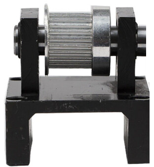
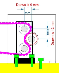
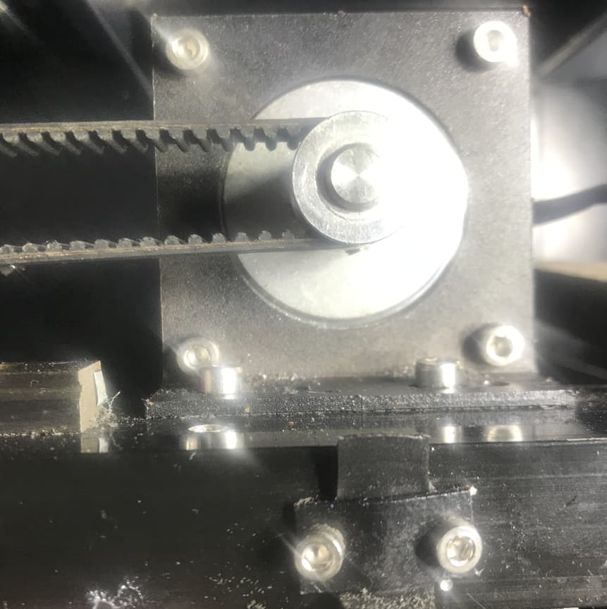
Look at the non stepper motor side of your belt, the idler pulley.
Does it have Gear TEETH like this, like mine did?
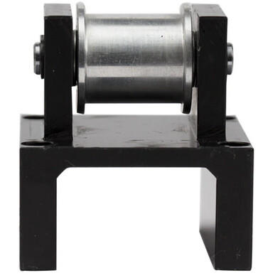
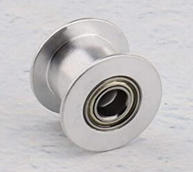
Then replace it with a SMOOTH pulley like this:
All I had to buy was one of these on Amazon, and I no longer see the teeth in my engravings.
Big shout out to Russ for pointing out that the teeth cause Belt Climb, which when the gear tooth raises the belt UP, it slows down, which cause the laser to burn the material longer in that spot.
When the gear tooth falls into the belt, it grabs the belt, and yanks it or speeds up the belt, resulting in less time engraving the material.
Hence, being able to easily see the teeth on the belt in your engraving.
Just replacing the Idler gear on my system solved this for me.
it’s interesting to consider that the problem is solely caused by the pulley at the non-drive end. After seeing Russ’ method of reversing the wrap on the drive end, I wondered if it was necessary to go through all that work. Between then and now, I discovered a product line called synchromesh drive systems and also wondered if that would help reduce the curtains/banding. I saw a video of this drive being installed in a 3D printer design which worked well for the lack of stretch and light weight. I think it might work on a laser too.
The problem is it’s ‘climbing’ the tooth and dropping into place. Stretching and shortening the belt.
A smooth pulley at the other end won’t change the physics. It’s just not visible in the work he’s doing.
Right speed and power (so you can see the variations), I think it will show it’s nasty head again.
@CadJoe thanks for bringing it up. Maybe what you found has just added to the problem. This is probably a good idea to fix for anyone with teeth on the idler pulley.
Mine came with a smooth idler, why would you even put teeth on it?
Great question, but MY Red/Blk 5070 had teeth on the idler side, and I never knew it was wrong, but makes a huge difference on quality of engraves, why I posted this for others.
In changing to the smooth pulley, it completely solved my banding, regardless of speed and power, at least for now.
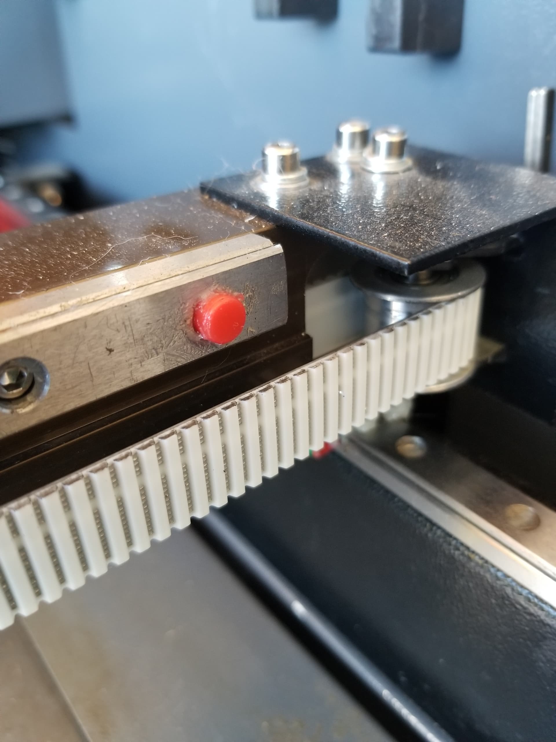
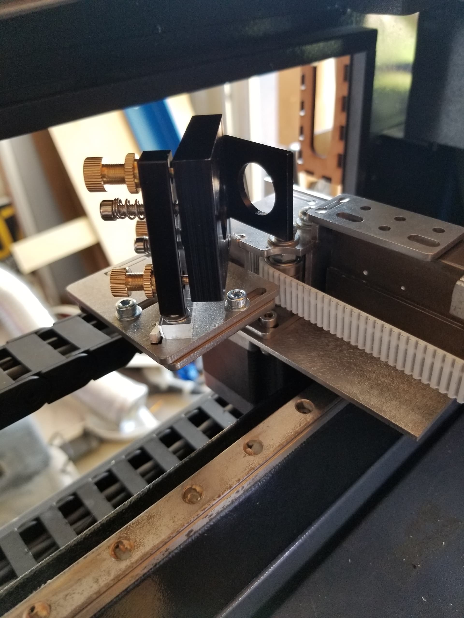
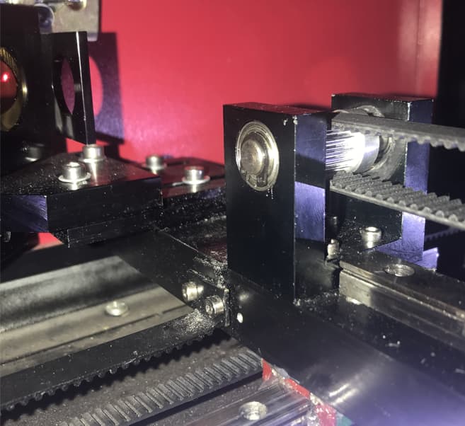
I see in your pic, the belt is smooth side down on the idler pulley, not sure how your stepper gear engages your belt.
That is Russ’ ultimate solution, is to flip the belt in a Stepper Gear config like this:
Russ had many of his items passed over by Cloudray, although they did do a few.
That’s kind of tough without money.
I would buy one if it fit ok, which is the problem. Mine is bottom barrel construction and I can see issue with it. So maybe it would be a good idea to manufacture.
Another thing Russ has mentioned is that identical looking machines can vary by 10mm in the parts…
Complicates the problem.
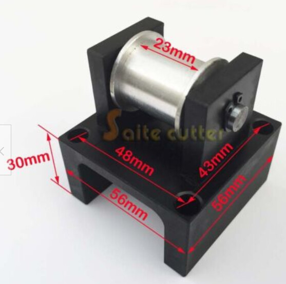
You mount looks kind of over engineered for a laser belt. Probably park my Jeep on it… lol…
Now’s the time to purchase a cnc mill and make’em yourself
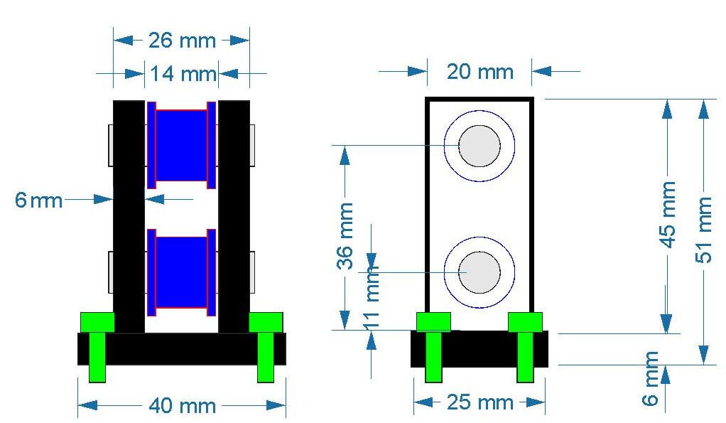
I wanted to be able to just slide it in front of the Stepper Motor so nothing else has to be modified, and maybe use the left stepper screw bracket as part of the mount.
I also noticed that if you have a Toothed Gear, the bearings are on the mount with shaft or axle going thru the pulley with spring clips.
But when you switch to the smooth pulley, its a smaller hole with the bearing in the pulley, not on the axle, and almost impossible to find the smaller dia axel with spring clip slots. So I just ran a bolt thru mine, and it works.
Check out hubs.com or oshcut.com. There are a bunch of others as well. You can upload your design and get an instant quote.
I’m guessing if you could modify your design to be cut from sheet and assembled or bent then likely cheaper than getting this machined from a solid billet.
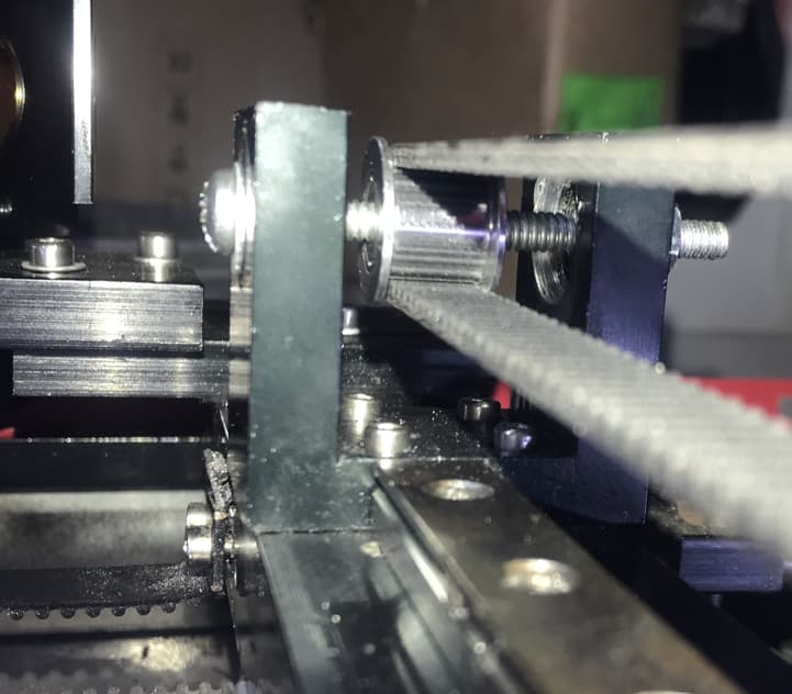
I’m surprised you don’t have trouble with the pulley wanting to travel up and down the bolt from the threads. You could also get an oversized screw and file away the threads if this posed a problem.
Oddly, it works and centers itself on where the belt wants to ride.
I did it as a temp solution, till I can find where I can get a new shaft/axle for the smaller diameter. Keep in mind the 2 Bearings are still on the ends too with the larger diameter, so I’d have to replace those with a smaller diameter hole as well.
If I can find a Smooth pulley with the side set screws, then I can go back to my original design using the original shaft and side bearings.
Making mods is SUCH a pain, problem after problem… hehe
However, my current setup is the BEST ever, with tons of Lens tube length and FL options, so love the changes.
Thanks for the links, I bet I can make it so the sides recessed bolt from the bottom, and then maybe have slots for the axle / bolt or whatever to adjust up and down to line up with the stepper correctly. However, with that said, just replacing that single pulley solved my banding, so don’t need the Rack & Pin design.
“belt climb” is caused because the distance from one pulley to the next is not a divisor of the teeth spacing on the belt, the tooth size or shape is poor or the tension is incorrect. Toothed pulleys go into teeth, flat pulleys are for the flat side. Flat pulleys on teeth will cause premature belt wear and possibly vibration.