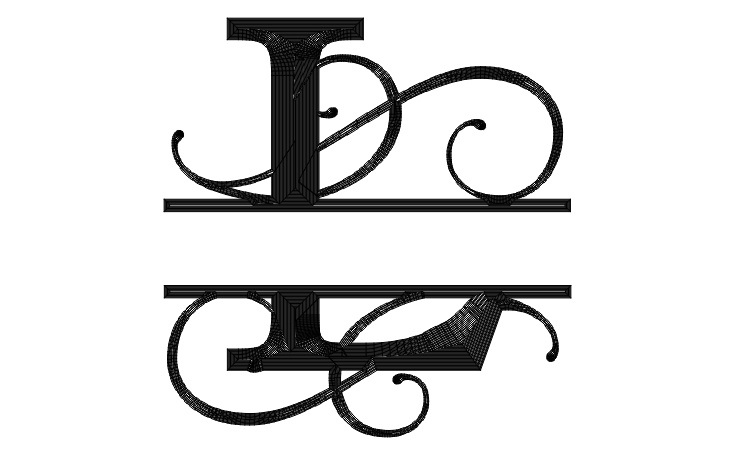
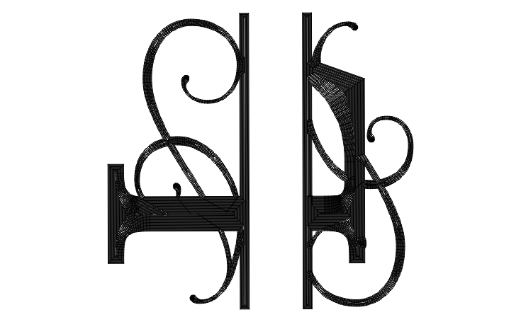
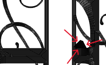
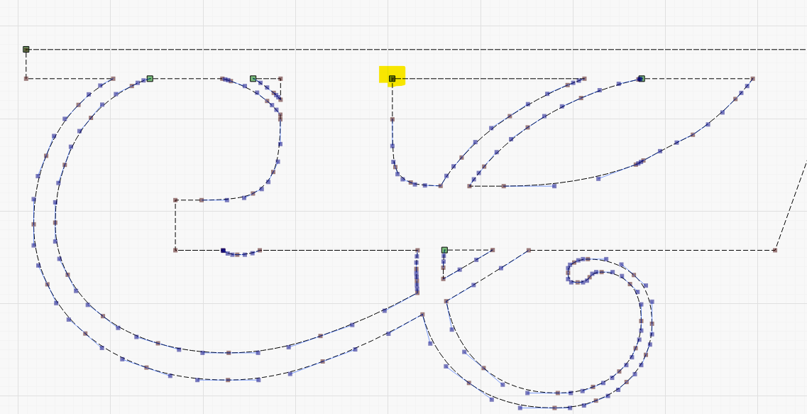
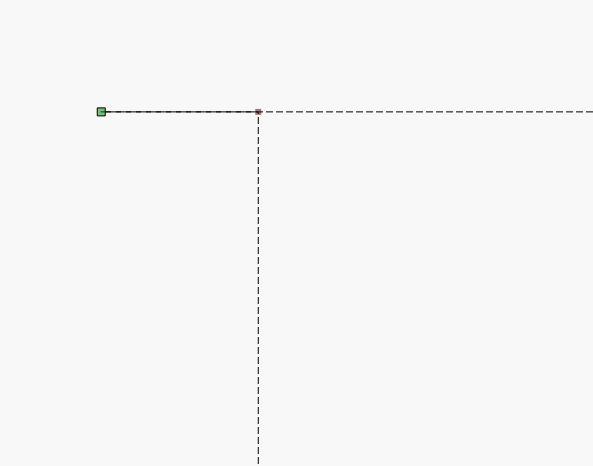
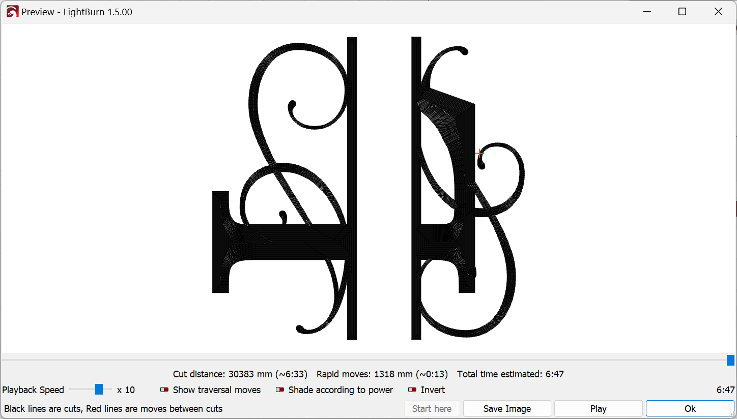
Hi, I’m new to Lightburn and diode lasers in general but I’m enjoying learning the software and the technique. However, I think I may have found a bit of a bug in the software, or I’m just being stupid, which is probably the more likely scenario. Anyway, I have been trying to work out how to engrave drinks glasses. I have a rotary roller and the set up requires that objects or text in Lightburn work space are in a vertical orientation rather than horizontal. I had been manually rotating my objects (a letter initial) using the “handles” at the corner of the selection. I wasn’t overly keen on this as I sometimes didn’t orient the text at exactly 90 degrees as I was wanting to do. Belatedly I realized that I could just type in 90 degrees on the “rotate” tool bar and everything looked perfect. Except!! that when I opened the preview window to see how the engraving was going to run I think I noticed a problem. I have attached screen shots of the preview windows showing a) the initial in its original horizontal orientation, b) when I rotate the initial manually, and c) when I use the digital “rotate” option. As you can see, when I use the digital option its as though some of the laser pathway doesn’t rotate uniformly (arrowed). Am I just doing something very basic operation wrong, or is there a bit of a problem with the rotate option? I did wonder if this may be just a problem with how the preview window presents the image but I don’t want to waste drinks glasses just to find out and even so it’s something that may need fixing so as not to confuse people like me.
How are screenshots 2 and 3 generated differently? Are you saying you get different results at different times for the same orienation?
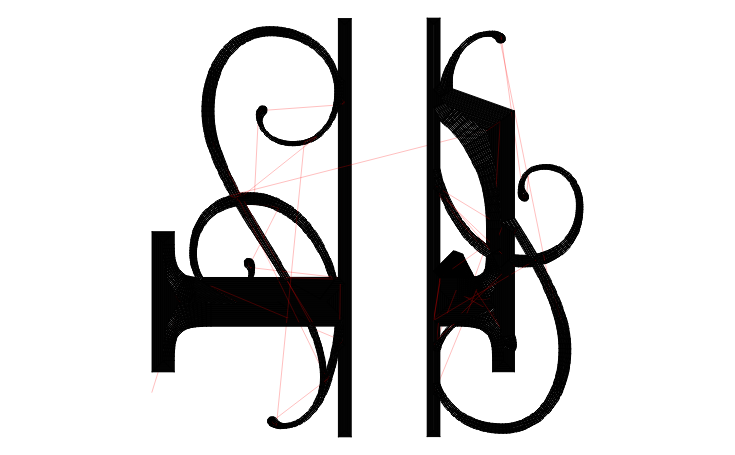
In any case, looks like you’re using offset fill. Note that the fill path for offset fill is not considered part of the geometry. So the particular fill I don’t believe is guaranteed on rotation.
As an aside, note that you can use ‘,’ and ‘.’ to rotate selected shapes CCW and CW respectively.
I’m not sure what happened when I loaded screenshot 3, it should look exactly the same as 2 except for there is now an area arrowed where the path seems to deviate from expected. Nothing is changed in any parameter other than the way that the initial is rotated.
One thing to add: if you are using a rotary, do not use offset fill. Always use normal fill and scan along the x-axis of the object. The rotary should only do minimal steps at a time and the x-axis should to the movement. Objects on rotaries tend to slip, so minimize movements in y-direction. Some remarks about this are here: Rotary roller - Diode Laser Wiki
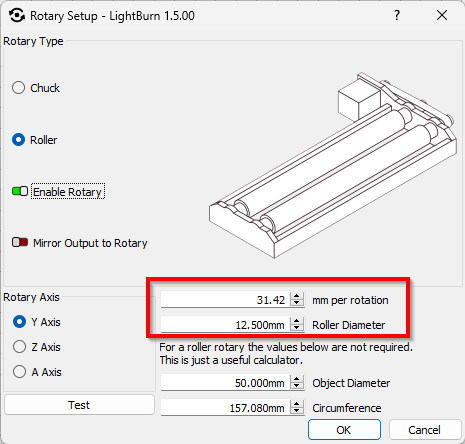
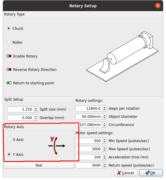
Thanks for the heads-up Melvin. I am still working out how to use the rotary and any tips really help. At the moment I’m trying to work out why when I use the “test” setting in the rotary set up window my work piece doesn’t turn anywhere near a full rotation despite the fact that I am using the rotary settings recommended by the manufacturer (Longer).
Thanks for the info, i was beginning to think that it was one rotation of the roller and that the distance traveled should then be ~6.28 x radius. I guess im not getting what the calculation is that determines the distance traveled by the item on the roller. I plugged in the numbers that Longer gave me for the roller diameter and distance traveled in Y, then the diameter of the glass and the gui gave me a circumference for the glass. But when i made a test oblong with the same length as the glass circumference the ends dont meet up and im unclear which parameter to adjust to calibrate the roller. It doesn’t matter if im only doing one engraving, but i want to do equally placed engravings on opposite sides of the glass and for that i need precise calibration i think.
The most simple way is to mark the roller, press the test button. The roller should start at the mark, rotate to the mark and rotate back to the mark.
There is absolutely no reason to involve diameter with a roller at this level. This complicates what should be a relative simple setup. I will use the Y axes for the examples, but it really doesn’t matter which axes you use.
Fiber rotary setup has an option to pick which axes is rotating.
The rotary, either type, makes it look like the Y axes to the controller. If the head moves 10mm on the table it should rotate the objects surface 10mm. This is call surface speed and is why the diameter is needed to compute this.
With a roller it’s much more simple and once set works forever.
As an example, say you have a 10mm object. On a table the y axes move the table, now you hook the Y axes to the rotary, which is now the rotary.
The rotary is configured so it’s rotation will move an object resting on it the desired amount. This is a wheel driving the surface of the object.
A roller works with no other modifications, no matter if you put something the size of a pencil or a 55 gallon drum on it.
It might help us if you can provide the link to how the manufacturer wants you to set this up.