I want to use the 5V pwm that normally goes to the laser diode to control a microservo. Should the OLM2/s2 mainboard support the current draw of a microservo (100-300mA?) from the 5V pinned onboard regulator?
Most pwm output are designed to drive optical couplers at the < 20mA area…
One of my boards can drive a spindle of about 250mA, but that’s it… doubt yours has a spindle ability…
To be sure, you’d have to ask the manufacturer… doubt they’ll give you any information, but I don’t know.
Do you mind explaining what you are doing…?
It sounds like you’re going down a tough path here. There might be a more simple way …
![]()
My thought was to use a microservo to manipulate a pen to make it a plotter. Something like an SG92R.
I hadn’t considered any current limitation on the pwm signal. I don’t see any info on the current draw for the SG92R signal pin; I guess I’d need to measure it? I didn’t expect it to be significant.
I’m unfamiliar with spindle servos, but maybe you were expecting I had something more like a cnc in mind?
The pwm is used on a cnc machine to control spindle speed. This isn’t present on your control board, it’s used to drive a laser module so components for a current hungry spindle aren’t on the board.
How is the pwm going to change your pen movements? Usually plotters with a pen are either pen up or down … nothing in between.
Servos are relatively expensive for the mass they need to move on these, so it seems few people use them…
Do you have a servo controller of some type?
There are a number of people around who’ve done this and have plotters… I don’t know exactly how they did it… Might edit your title to include pen plotter… this might bring in some of these people that have done this…
Good luck
![]()
Yeah, I’m not aiming for something as heavy as a cnc servo. An SG92R is $5. That’s fairly affordable to me.
I’ve been looking for any info on laser engravers being converted to plotters and haven’t found any useful info so far. I’ll try the forum search here.
I plan to replicate something like this: https://www.aliexpress.us/item/2255800855535843.html?gatewayAdapt=glo2usa4itemAdapt
I don’t think I need a dedicated controller; the microservo uses a pwm signal as input to indicate the desired angle of the arm. The control circuit is built-in. I can limit the angle range in lightburn and have lines drawn from vector images at certain %pwm to correspond to ‘pen-down’. The output from the OLM2/s2 mainboard normally used for the laser could be sufficient.
I see what you’re up to now… you’re using an rc servo… I was going in an entirely different direction.
Does this just lift the pen?
![]()
Cool, sorry for the confusion. Yes, it just pushes up the pen. There’s usually a retaining spring to provide downward force, and the servo just keeps it lifted.
When it wants to lase, it generates a pwm… but the servo doesn’t really work on pwm, it’s based on pulse duration… I’m not up on these these, so that part is your problem ![]()
From this Adafruit article on using these
Position “0” (1.5ms pulse) is middle, “90” (~2ms pulse) is all the way to the right, “-90” (~1ms pulse) is all the way to the left.
They show it connect directly to an Arduino and power, indicating it’s a control signal and probably doesn’t draw much current…
Adafruit stated, for power, holding current is low, but the power may need up to 800mA. You can look at the code there it doesn’t appear to use pmw. The signal current appears to be low enough for an Arudrino.
The Arudino is also a 5V board and the controller you have is likely 3.3V, so it might be a problem there…
Good luck
![]()
My understanding is that its effectively also PWM, as in modulation of the pulse width provides control? If I set the pwm frequency to 20 ms, then 10% power would be 180.
My controller board has 5V pwm output for the laser control, and a 5V output on the connector that seems to have been intended to be used for z axis (not sure how it would have been used).
I’m less worried about the control signal, and more worried about the current draw from the 5V provided by the mainboard.
RC servos set their position via PWM. Typically 0-100% determines their rotary position. If the power limits are ok, a laser-off or laser power at %5 or so will move the servo to one limit, then a 100% laser power will move it to the other limit.
Servos typically have a dedicated power and ground and the PWM is just for the positioning signal.
Thanks for jumping in… I just read the specs on the site as I have no experience with these…
Will your controller go down to 50Hz (20mS) for a pwm frequency?
Have fun
![]()
That’s a good question. Ortur doesn’t give much info beyond the standard stuff. The Ortur laser modules expect 1000Hz. I don’t have an oscilloscope, so all I can do is try it out?
I mostly wanted to avoid the possibility of damaging the mainboard ($70). If this doesn’t work with the ortur mainboard then I’ll just have to replace it.
RC servos can handle a bit of range in the control frequency. Radio systems generally used a rate of 50Hz, but the servos can typically accept up to a few 100 Hz.
Since you seem to not be concerned about positioning so much as a pure up/down, you can simplify things and get a much faster response with a solenoid.
How fast do these respond… The controller, I assume, would think it’s time to write, it’s still moving and we’re past the point it’s supposed to write before the pen is lowered…
Just wondering…
![]()
They are not “fast” by any means. If you have ever watched an old pen plotter (the HP desktop units come to mind), the pen up/down actions are very fast. A typical mechanical setup is the pen holder attached to the “X” axis rail (just like many gantry style lasers) and the entire rail is rocked with a solenoid for the up/down motions (reducing weight to improve response times).
I suppose WRT Lightburn control, the overscan parameter could be used to compensate for a slow servo but that up/down motion would be a fairly long ramp versus a quicker snap action.
The more I think about this, assuming the desire to have a pen attached in place of the laser module, the best solution might be to salvage the pen holder unit from a plotter and mount that with the accompanying solenoid. The laser has the power line which should provide enough juice for a solenoid and the control signal (PWM) could activate a MOSFET or other device to drive the solenoid up/down with laser on/off commands.
Using a solenoid is probably a great idea, actually. However, if I get a 5V solenoid, I still have the original problem of not knowing if the mainboard will support the load on the 5V regulator.
This mainboard also has some weirdness. It has a 24V supply, but when connected by usb it also powers on, so I’m a bit worried about how the 5V power is done.
The voltage to your laser module is probably the same as the devices main power supply (24v). This probably runs directly from the power input and relies on the regulation of the power brick. Internally to the laser is further regulation circuitry, but the key is you should have ample capacity from the laser harness. I’d try and trace the laser power source to confirm, but you can easily run external power for the solenoid if needed. The laser’s PWM supply is limited and I wouldn’t want to rely on that for triggering directly, that’s why a buffer circuit (opto isolation is a good solution) between the PWM source and mechanical device used to activate up/down.
EDIT:
Had a look at a spare MB for my OLM3,
The 24V from the power brick runs to the laser directly, with a MOSFET acting as switch that allows the controller to turn the power on/off as needed.
Convinced that there are easy to use isolators for just this type of application, I found these
You can run an external power wire of the required voltage/power to the solenoid and you should put a diode across the solenoid coil to snub the voltage kickback.
Yeah, I get that I can’t use the pwm as a supply. There’s another connector off the mainboard that seems to have been originally intended for a z-axis. That connector has a 5v pin, but I can’t trace where the regulator for that pin’s supply is. I can’t identify any component on the mainboard that is supply the 5v (or 3v), so I can’t determine if its reasonable to draw from the mainboard’s 5v supply to power the solenoid.
I understand the need for a mosfet or similar isolator, and the need for back current protection. Mainly I’m trying to figure out the best way to provide the supply voltage for the solenoid/mosfet.
I could definitely get a separate 5v supply for the solenoid. It just seems like overkill when the mainboard might give me what I need.
EDIT: the connector is here (lower left, red box)
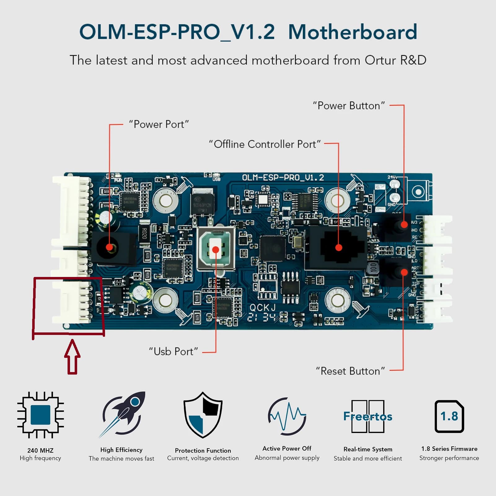
EDIT2: Since I’ll need some additional electronics for the solenoid anyways, maybe I should just get a buck converter and draw from the 24v?
I understand the desire to just use what us available. The photo makes it look like that port has it’s own regulation, the electrolytic capacitor is usually associated with a nearby voltage regulator. If so, you might have 100+ mA of current available but I’d hesitate to have a solenoid coil with the associated voltage spikes being fed from that.
With the device I linked to you could run the solenoid off the 24V supply if that meets the requirements of the solenoid, or better, just get a second power supply.
The device will keep the PWM requirements low and leave the higher power stuff to be handled by external circuitry.
I wouldn’t try to convert the 24V as it would be a lot easier to just get a wall wart type supply of the proper voltage and current.
You know what, you’re totally right. It felt a bit silly at first, but it’s probably my best option.
I think you’ve both answered my questions. Thank you for your patience and time. ![]()