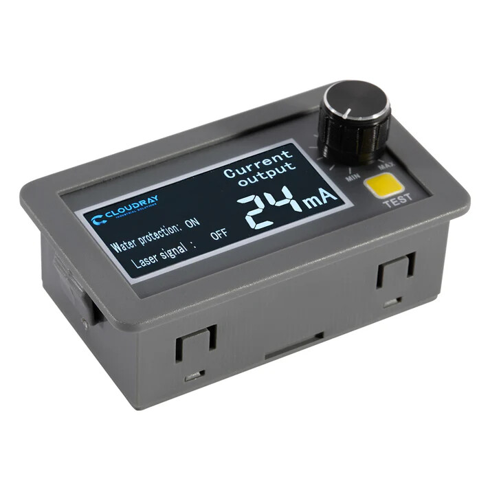
I have a brand new Gweike LC6090 laser cutter with 80W RECI laser tube and Ruida RDC6442 controller. There is an ammeter mounted above the controller.
According to RECI the maximum current draw for the 80W tube is 24mA. When running a job set at 90% power, run straight from Lightburn, the Ruida display says the maximum power is 80%, and the ammeter reads 32mA, not the maximum safe 24mA.
Please can someone explain what is going on here? Gweike have set me up with a DingTalk support group. The one chap says not to worry about the current draw. They also say there should be a knob mounted underneath the ammeter to adjust the current, but there is not. There is also no obvious power adjustment on the laser power supply.
How do I adjust the power down so that I can use the full percentage range in Lightburn but not exceed the 24mA?
As far as I know, it can only be adjusted in the power supply itself. Most have a small hole with access to a potentiometer.
Btw. if the manufacturer recommends 24 mA I will also stick to that.
You can limit max power in LB but it is only a “stop” and not a rescaling.
The knob varies the tube current from 0% up to whatever the controller’s PWM output specifies.
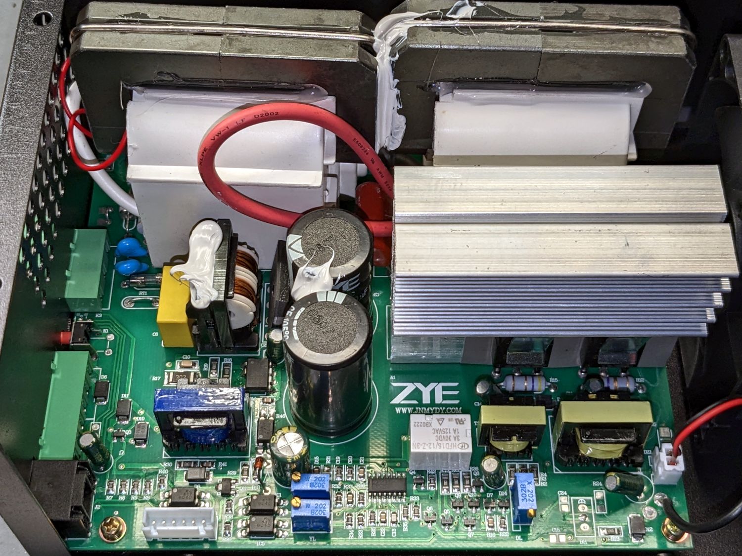
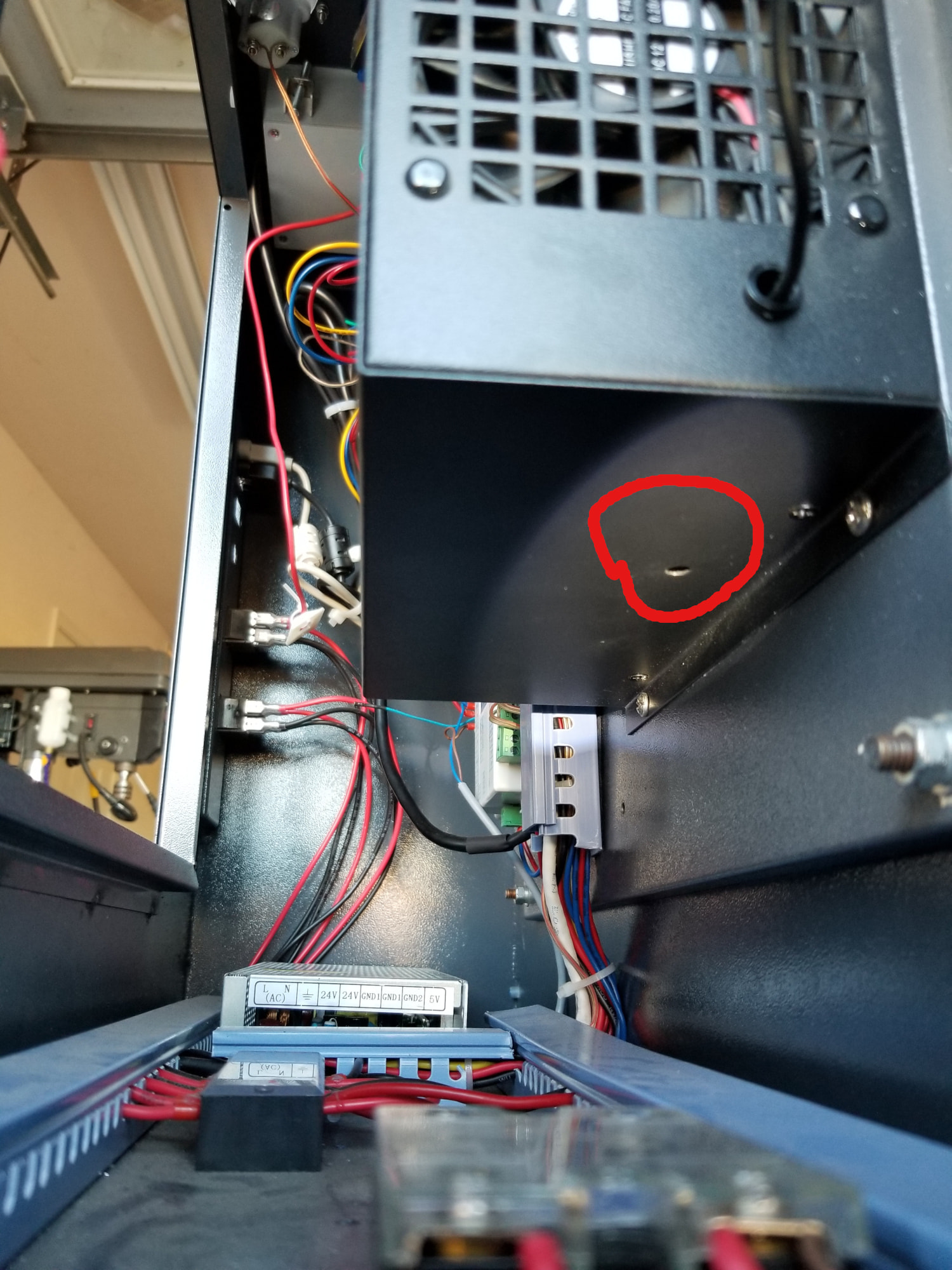
As @bernd.dk notes, the high voltage power supply will have a small round hole giving access to an internal trimpot setting the maximum output current. The small blue trimpot at the lower right of the PCB is the one:
The hole is usually in an inconvenient (sometimes invisible) position when the power supply is mounted inside the laser. In my machine, that side of the supply faces down with a few inches of clearance.
Assuming you can get a small screwdriver in there, the adjustment is straightforward:
Set the controller for a 50% power manual pulse
Power with Min/Max button
Duration with Z/U button → Laser Set → Continue
Note the current on the meter during the pulse
Maximum current = 2 × that value
For your machine, adjust the trimpot so the current is 12 mA = ½ × 24 mA
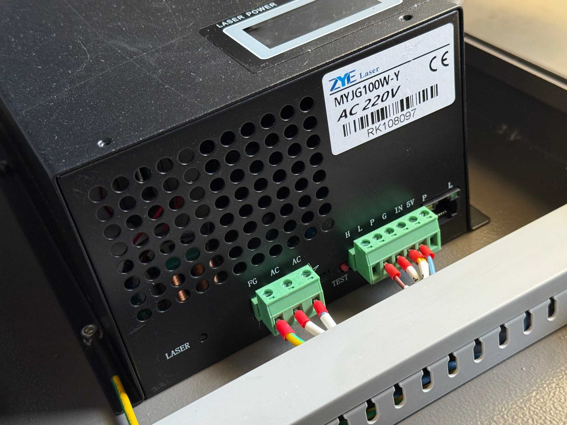
This is my power supply, a ZYE laser myjg100W-Y. 100W in the description but the specs say it is suitable for 80-120W. I found the manual online, it says nothing about adjusting the power. There’s a little hole next to the ‘laser’ label at front left. Changing the phrasing of my Google search yielded an AI-generated result that indicated that on some models of this power supply there is indeed a hole labelled ‘laser’ that is the adjustment point. I will give it a go. The goal is to have long life from the tube but to also have a linear output from different power settings in Lightburn for accurate cutting and etching / engraving.
Small note, if you have the possibility to open the box - do it. If not, you have to fumble your way to the small pot and there is a risk that you short something - use a ceramic screwdriver.
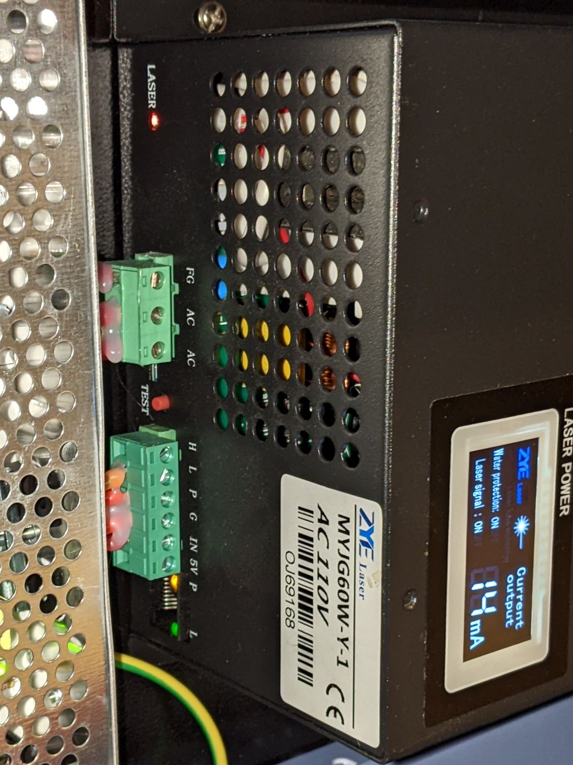
And to make it even more interesting , some power supplies with internal mA meter have their pot on the side and not at the mentioned hole in the shown position next to the green sockets.
The unmarked hole you want is on the right side of the case (as shown in your picture) and likely inaccessible due to the wiring raceway (or whatever) a few inches further right.
Of course, trusting randos found on the Interwebs is also risky, but …
Thanks @ednisley and @bernd.dk Yes the potentiometer is not behind the hole marked ‘laser’ but behind the unmarked hole down the side. The internals look similar to Ed’s photo. I did have to remove the power supply from the machine and remove the cover to identify and adjust the potentiometer. I would have to drill a hole in the frame of the laser to access the potentiometer with the power supply in place. I will do that at a later point. While the power supply was out I turned the potentiometer screw down a few turns, reassembled and tested. With the Ruida power set to 100% and 90% power in Lightburn the current draw is 24mA, the maximum recommended, so I am using 90% as the maximum. At least I now have a linear change in output power across the range, with the Ruida power percentage matching the Lightburn setting. I will remove the power supply again soon and wind the potentiometer screw down another turn which should allow me to take the Lightburn power up to 100% for better adjustability.
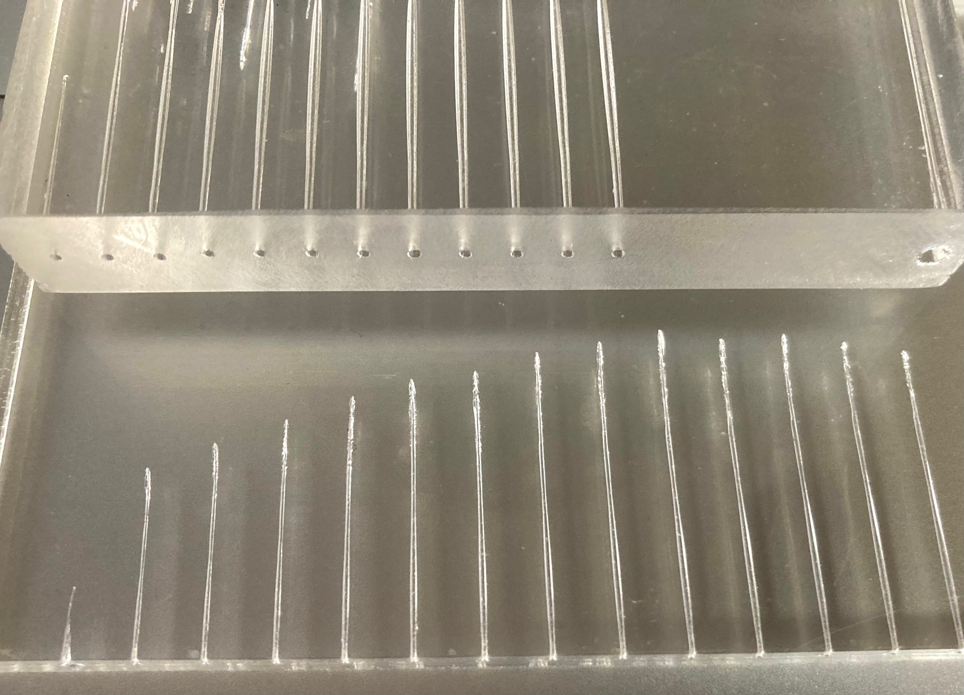
Small recommendation, now that you have reassembled your machine/power supply. If you can find a piece of thick acrylic, you can stand it on its edge and test your tube to find its real power curve.
I used 5 or 7 sec pulses, can’t remember. But my max power with this tube was achieved at 65-70% and 17-18 mA, after that the curve flattened out. So in my opinion there is no reason to pump more energy into the tube than necessary to achieve max power - at 70%.
I extremely rarely go above 16 mA and the tube has so far not lost much of its original power.
So my maximum is set to 18mA, not because I am “conservative” but because that is the (my tubes) physical actual max.
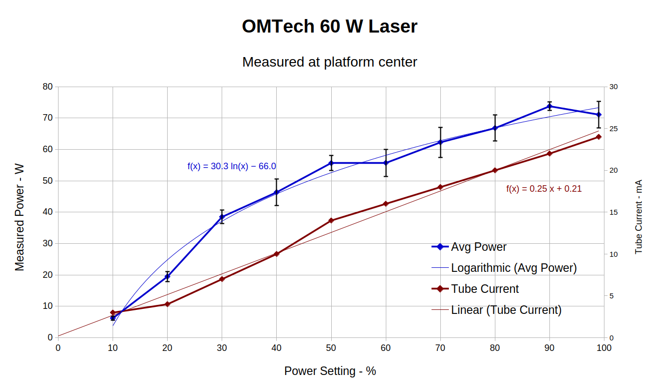
The power supply regulates the tube current (red curve) linearly with the PWM percentage, but the optical power (blue curve) shows most of the power variation happens below 20 mA. Not only does more current not produce much more power, the beam quality deteriorates.
I built most of my Material Table entries before I had the meter, but if I knew then what I know now, I’d adjust the power supply for 20 mA at 99% PWM (by setting 10 mA at 50% PWM) to flatten that curve.
Nice documentation and a great advantage to have a power meter.
What surprises me is that your curve doesn’t flatten out more.
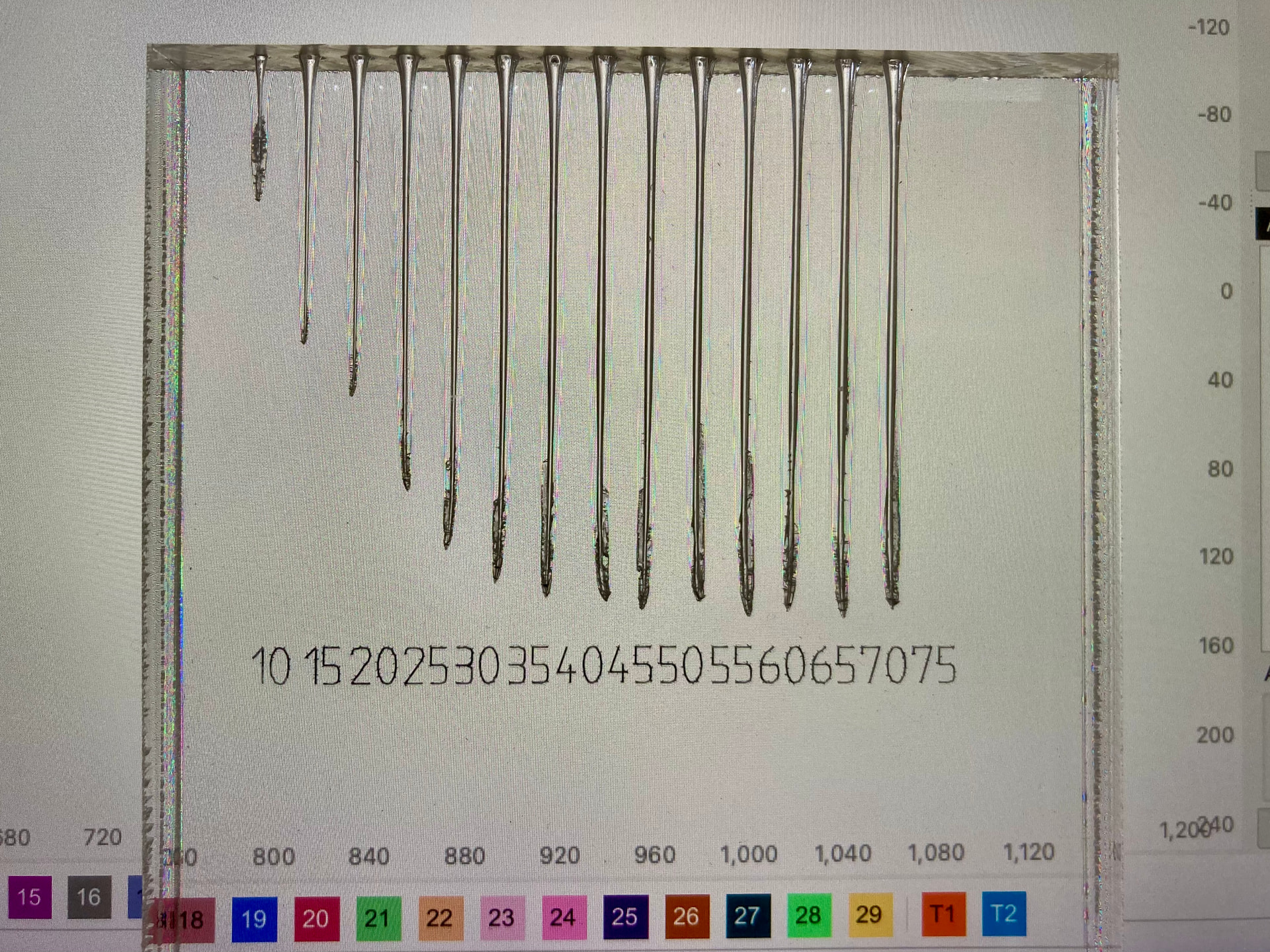
I did a new test today to make sure I’m not remembering wrong. The geometry of the curve is not much different from my old test, but I’m surprised that my power range is relatively low, i.e. 15-17mA is max here with this tube. However, I’m reasonably convinced that I get around 60Watt - bar at lower mA values.
It could be interesting to measure the true output, but on the other hand I don’t have enough practical use for it and to invest in an expensive measuring instrument.
Bottom line, it’s important to have a good tube that can cut and limit the tube from unnecessary overload, in my opinion.
PS a completely different little detail, notice the small cracks in the numbers, that’s material stress after using alcohol to clean the residue from the marker pen.
You can also set the pwm limits within the Ruida controller and limit it there. The best procedure is the one @ednisley described using 50% power.
There is usually two current levels described. One is operating current, which is where the tube maximum output is derived, maybe and do not exceed current.
My 50W tube will produce 67W at it’s do not exceed limit. Mine is setup to produce 25W at 50% power, not based on current but on watts out.