Power scaling on Ruida RDC644XG––I have some questions

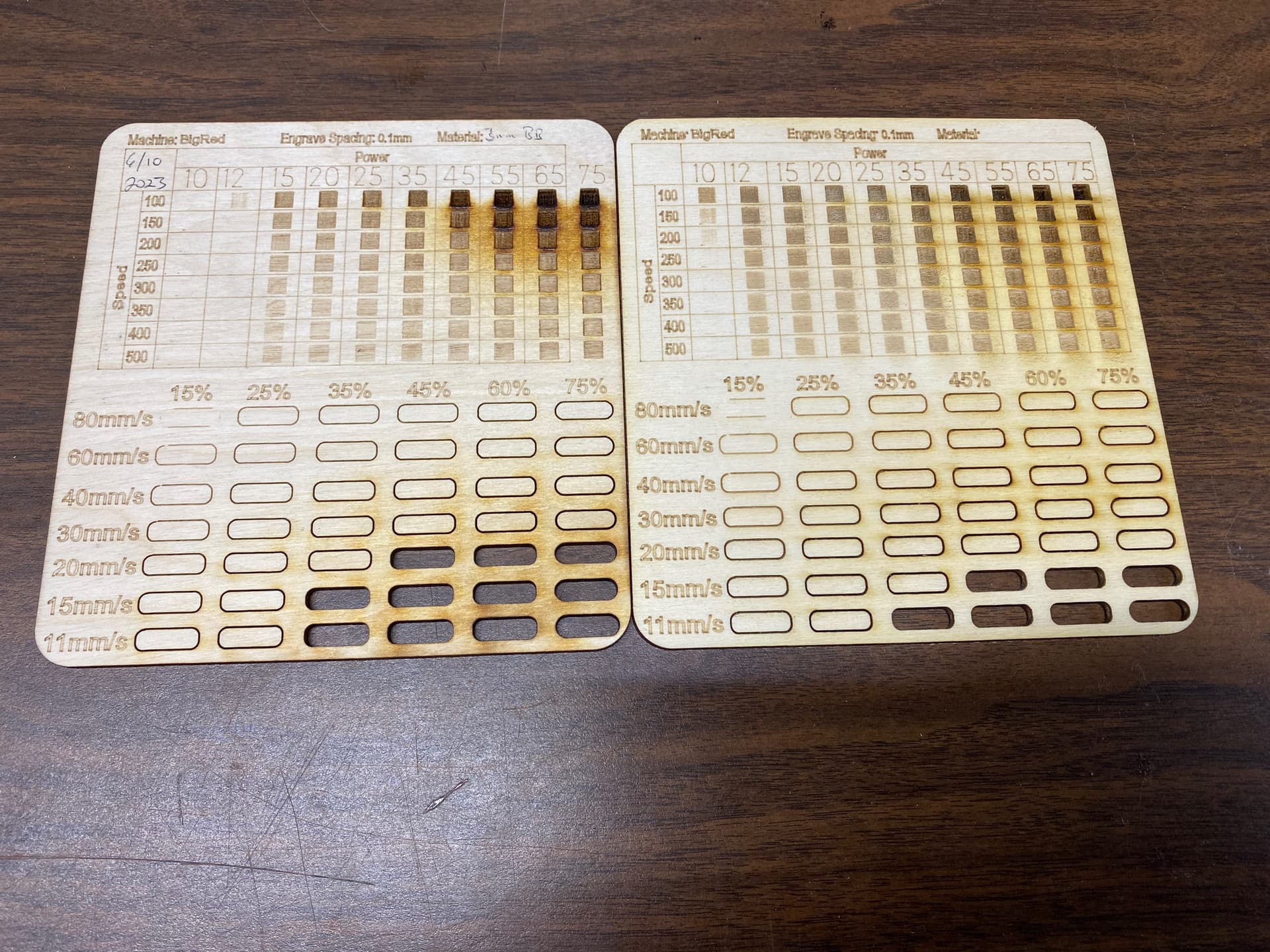
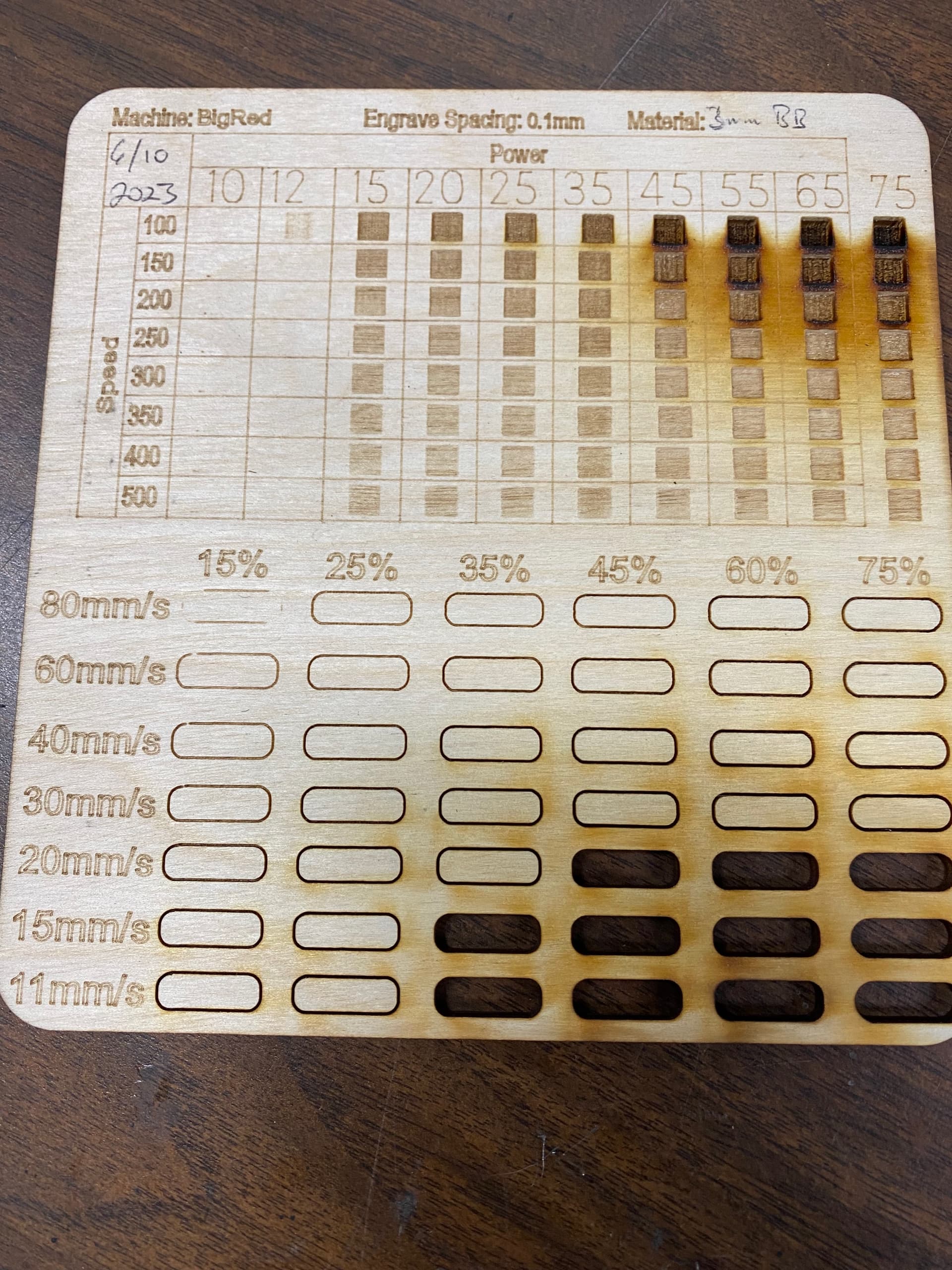
I picked up one of these test grids a while ago and run them on different materials on the different lasers in our makerspace. In each row, all cut or engrave shapes are set to the same speed with power set to max 100% and min 0%, then each shape is power scaled by column. The numbers at the top of the columns are equal to the power scale number of that column.

I get better results on the test grid than I do in real life. For instance, in the photo uploaded, it looks like you should be able to cleanly cut through 3mm baltic birch at 20mm/s @45% power. In reality, I can reliably cut through the same material at 75% power at about 18 mm/s

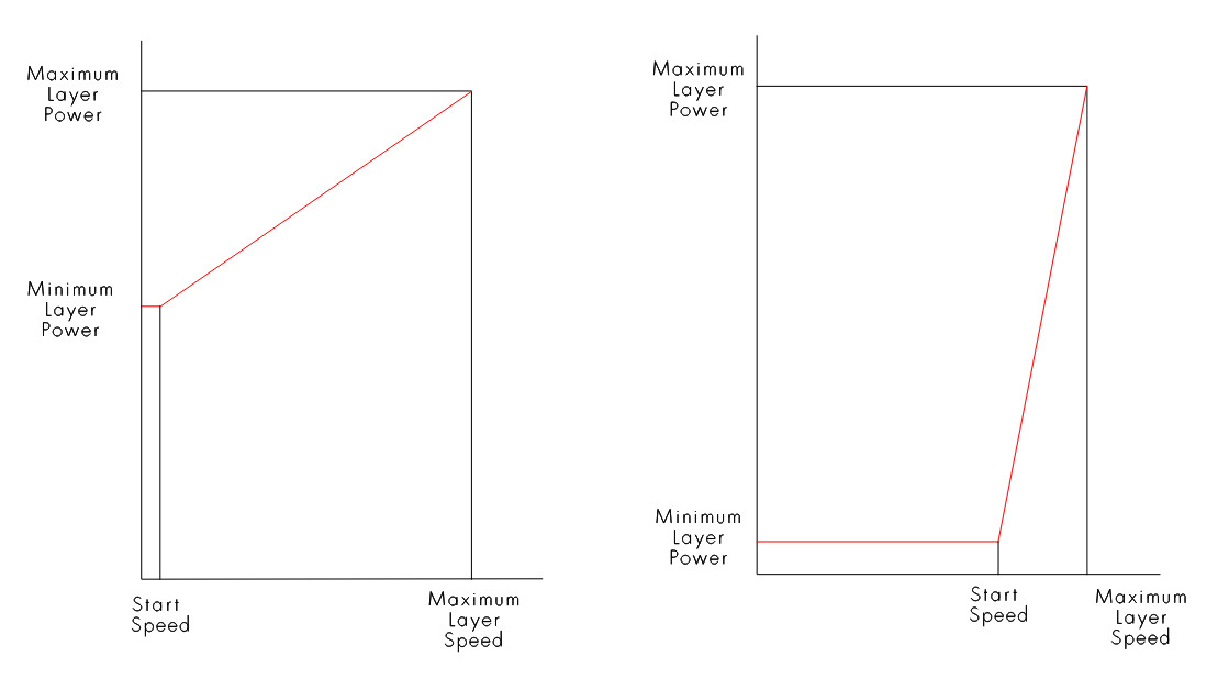
Via Lightburn, I’ve set the max power allowed on the controller to 75% in order to cap the amperage at 25mA. (We’re in a busy makerspace, so I need to keep the parameters enforced.) So I’m wondering if this may be the source of my problem. My power scaling range is between 0-100%, so when it cuts at 100 max/0 min power, power scale 75%, is it giving me the same power output as it would if I set it to 75 max, power scale 100%? If it’s not, then what would be the best way to get a more accurate result?
Laser speed and feed test file_BigRed 75max.lbrn2 (337.4 KB)


EDIT:
As I finished typing the previous paragraph, I realized that I could temporarily set the max power allowed on the controller to 100% and run the test again. That seems to give me results that are closer to our “real world” results. Anyone have a better understanding of power scaling they could share so I could understand just what’s going on? Thanks!

Whatever is set within the controller is what you will get for maximum.

If it’s 75% then that will be the maximum pwm that will be generated… no matter what you set it too.

The proper way to set this is via the lps internal current control


Minimum and maximum power is relatively applied in reference to the start speed in the controller…

You would have to ensure that every laser is set to the same values in the Ruida controller.

Even this won’t give you same results… one tube might lase at 10% power and another at 20%… one is probably not aligned as well as the other and/or might have not 100% clean mirrors or lenses… The lps might not respond as fast on one machine as another…

Any of this make sense?

:smile_cat:

So the short version of your response is that this is a fool’s errand and I should try something else entirely?

So is this different from setting the laser 1 max power in the machine settings in Lightburn? Would this be a potentiometer on the power supply? And why is it called “lps?” Is this referring to the high voltage power supply?

This is enlightening generally, but I’m not seeing how it relates directly to my question of trying to replicate 75% max power using 100% max power scaled back to 75%. Could you please elaborate?

Thanks so much for taking the time to respond in such detail!

I wouldn’t say that… you just don’t completely understand how these work … yet…


We usually use lps (laser power supply) to identify the high voltage power supply used by the tube from the normal low voltage supplies of 24/36V found in these.

The lps power supply will give your tube all the power it can up to it’s limit. Generally, your lps can supply more current than is safe for your tube.

You can limit % power rate, but when you do that, it’s not a direct relation to what the tubes current is doing…

When I adjust mine… with an analog mA meter.

  1. use 50% power, via Lightburn or through the console… I use the console of the Ruida.
  2. adjust for half the maximum current you wish on the lps.

My adjustment takes a contortionist to reach it, but you only do it when you change out a tube or lps. These are like, 20 turn pots… so it takes a bit of twisting. I have ceramic screwdrivers I use… many people use regular screwdrivers… but it always bothers me to stick a metal rod in something that is supposed to produce 30kV… even though it’s probably safe…

Setting this up this way, aligns the percentage of power in Lightburn to a relative value for the tube current… In other words, if you set up this way and someone runs 80% power, they will get 80% power from the tube…

You can now set the controller not to exceed a certain value for both low and high power. If you don’t want anyone to exceed 90% then set the controllers internal limit to 90%…

I don’t know of any DC excited laser that will work down to 1% power, so the minimum level should be whatever the tube will start to lase properly. Mine is set to 9%, if it’s cold enough it will lase there… during summer is will lase closer to 10%…

The larger the tube, the higher the minimum levels turn out to be… generally speaking…


You need to understand the relationship between min/max values in the layers and the start speed.

Situations when you are doing vectors and the head will stay lasing but it has to slow down and speed up for the corners or other tight places, the minimum value will come into play…

When you do a scan (image) or fill, the head has an area called overscan where the head can slow down, change directions and speed up. You can see this if you enable show transversal moves in the preview screen. The hardware in the Ruida does this for you and is generally responsible for the slop error message you get…

Although this is for acceleration values… it’s used to speed up/down the head and shows how overscan changes with different acceleration values. It looks very similar to running fast, but finding it takes longer to do the job… it’s spending time slowing down, changing directions and speeding up… This is 40,000mm/s and 6,000mm/s showing overscan… it’s the orange area… Notice the overscan size and the total time estimate difference between the two.

Follow me?

:smile_cat:

This topic was automatically closed 30 days after the last reply. New replies are no longer allowed.