This motherboard and the panel are incompatible, if you use this motherboard, the panel cannot be used, and the current cannot be used as a reference, it can only be judged by the engraving effect. If Lightburn can control the software to emit light normally, it means that your connection is normal.
Neil
Monport
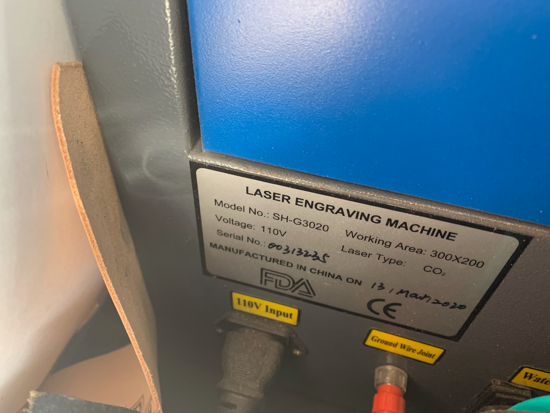
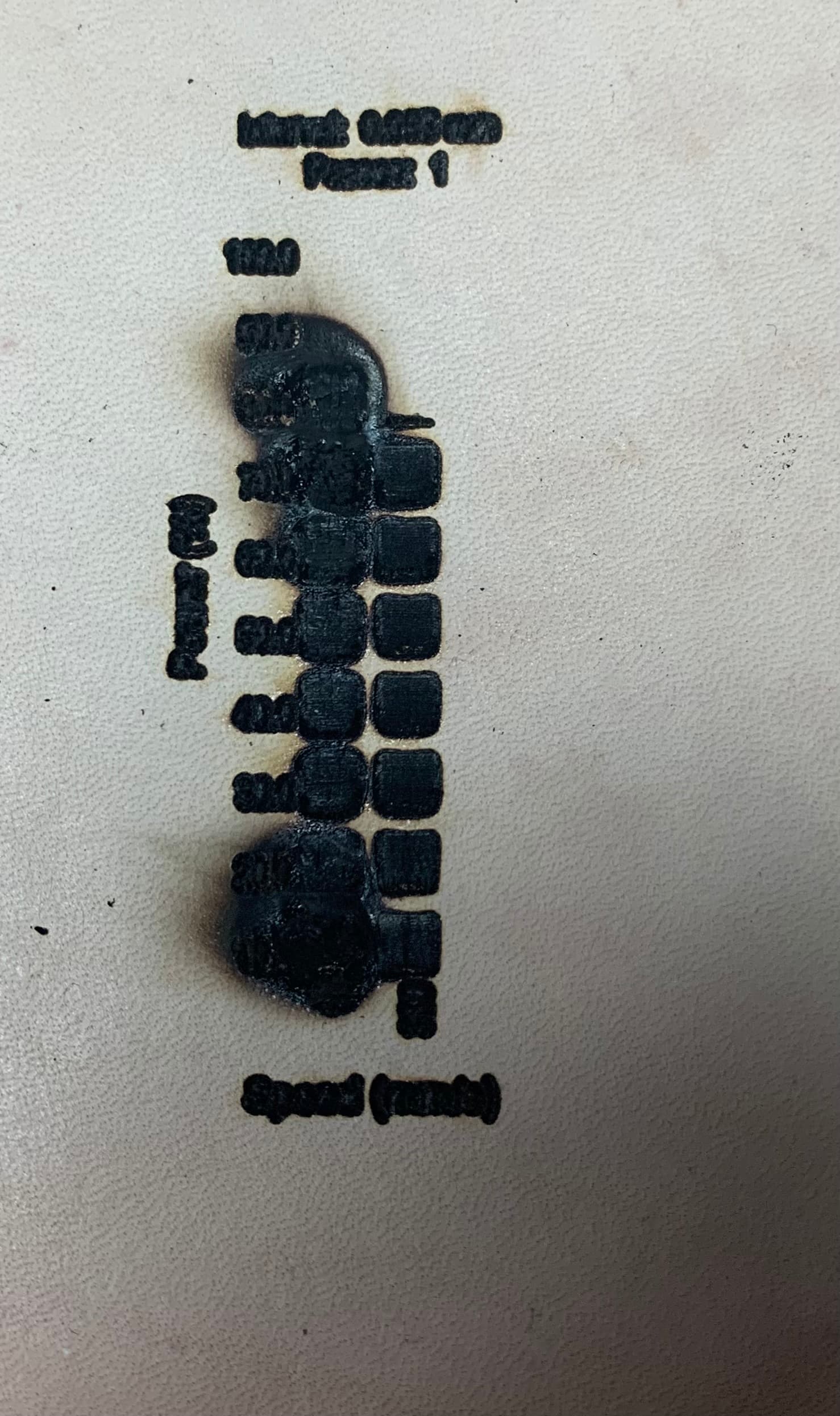
LY-2ax1s-5.0-V1.1
The change was to this board so I can use Lightburn
Wiring to change to digital with variable resister
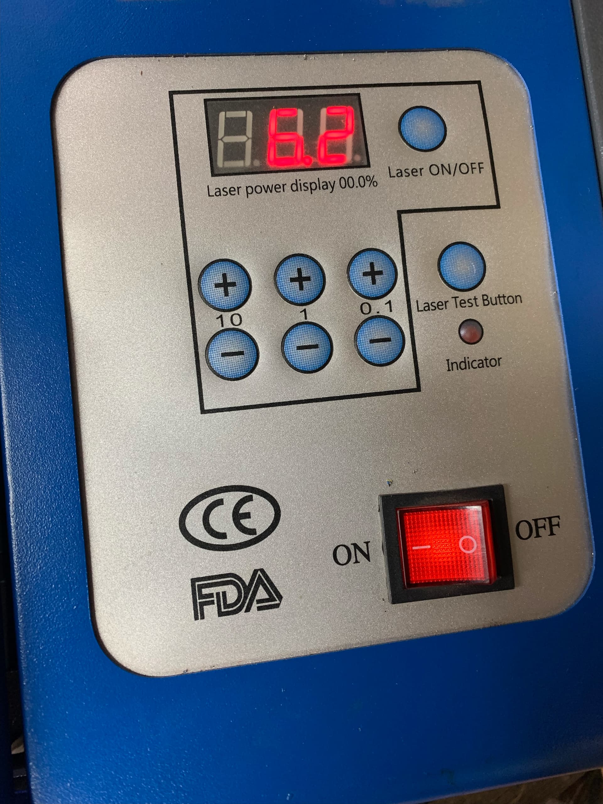
Does the version with digital readout & knob to control power still show power reading ( I read where you are suppose to set it 1000 & leave it alone)?
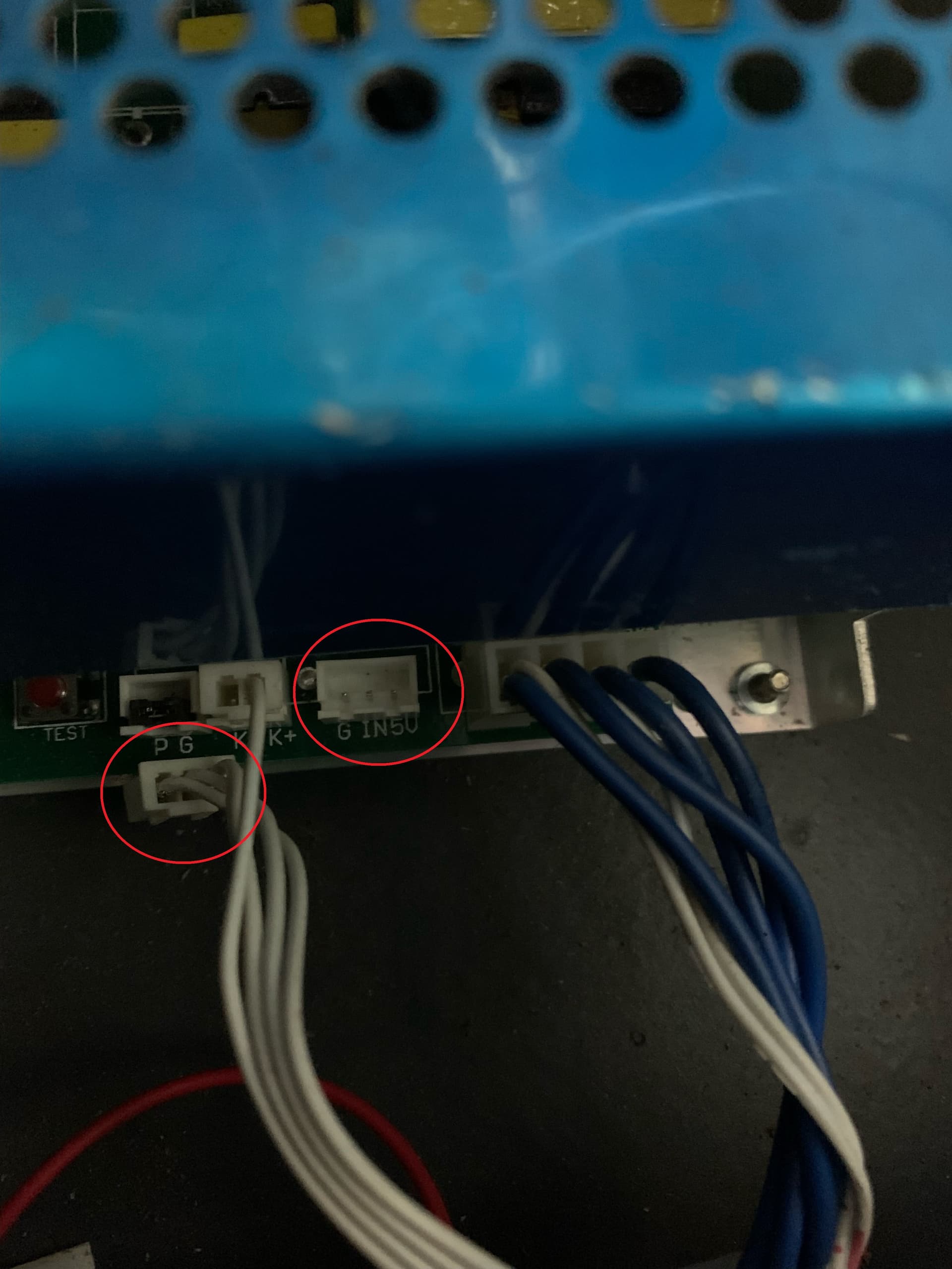
on mine the plug where the CBL Cable connects is where my digital panel is connected (G IN 5V)
I believe they’re stating that you cannot use the digital panel and the board at the same time which makes sense since it looks like they connect to the same connector on the laser power supply.
What is this referring to?
There are some units with potentiometers that plugin to a different port and can be used to attenuate power. Typically you’d set it to limit the top end of power and leave it there. I don’t know if there’s a specific value target.
Just confirm that the wires that are unplugged from the G, IN, V port lead directly to the digital panel.
Also, can you trace the wires from the controller PWM and GND pins and confirm how they are wired into G, IN, V?
Ok. In any case I’d suggest you test PWM voltage from the controller at a broader range of powers. If they don’t correlate to 0-5V that’s enough to demonstrate that the board is not working properly.
in that case you may be safe testing at the end of the cable but may be worth testing both ends in case you actually have an issue with the cable itself.
Can you run just a voltage test on the PWM pins? If voltage is not correct there you have no hope of this working. Disconnect cable to LPS and test at controller. The laser need not be firing at this time.
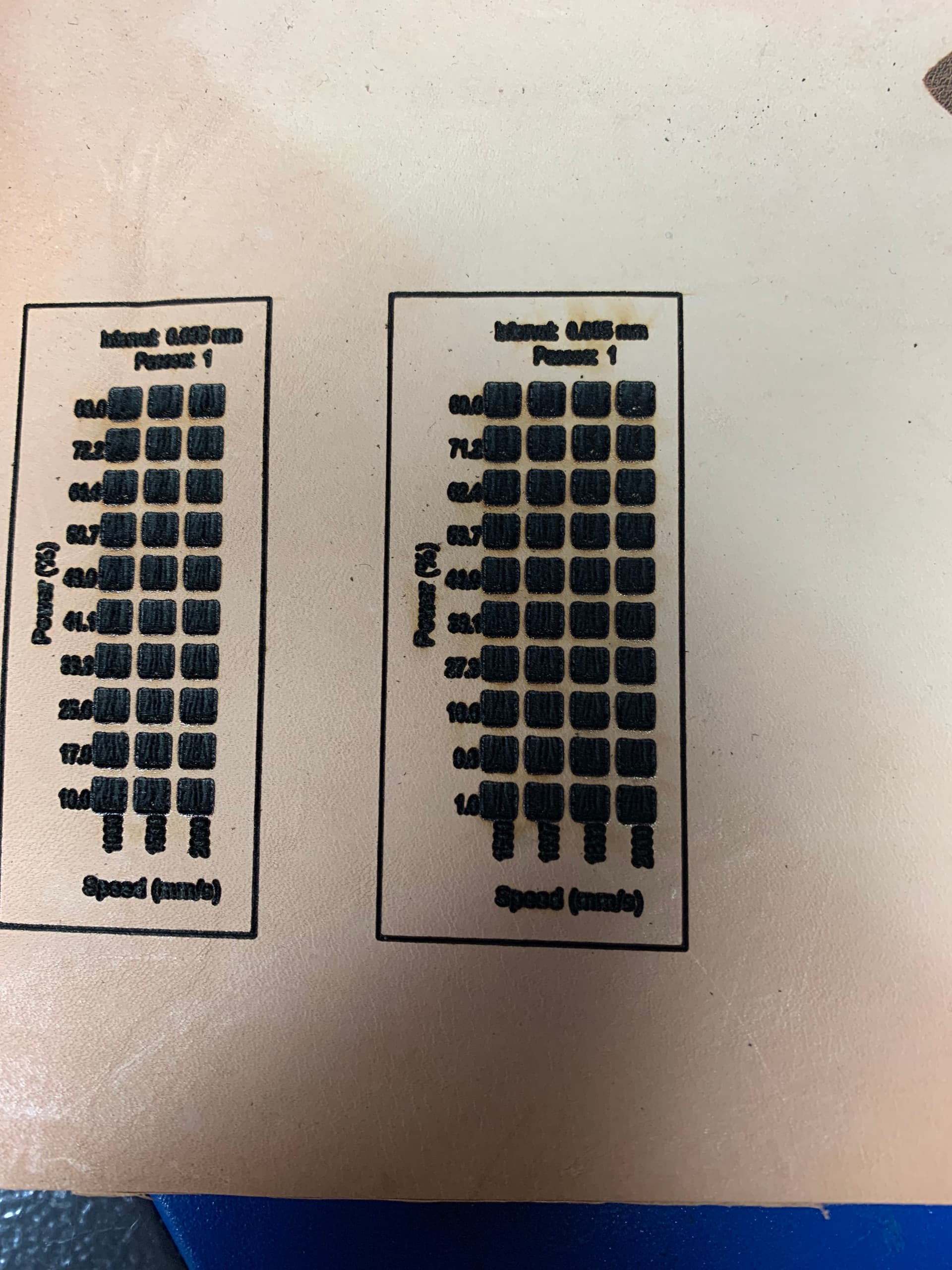
Create a large rectangle design in LightBurn, set speed to be fairly slow so that it gives you ample time to test voltages and enable Constant Power Mode so that variable power is not in play. Test voltage for at least 0%, 50%, and 100% power.
The key to this is what @berainlb has been driving at, if the signal from the controller isn’t right it won’t work. Stop wasting material and listen to him and you’ll figure this out…
changed to unlisted?
The volt meter was connected to the PMW Pins
There was little change until the outline
the 1st test was burning thru @ 10%?
the bigger benefit would be to point out what directions I missed?
Draw a line in Lightburn. Set your power and run it slow. This gives it time for meter readings to settle and for a human to read it. The first video of the materials test, I can’t tell what the pwm is, so there is little use to know what the voltage and current are.
Using known values of a TTL (0 - 5V) pwm signal, the output of the controller has to be a percentage of that.
At 50% pwm (power), it should read 2.5V at 20% pwm it should read 1V at 80% pwm it should read 4V. Any power setting you use should produce that percentage of 5V.
If these are not correct, then the problem is before where you measure it. The controller, including it’s hardware, but more likely it’s configuration, including Lightburn.
If the voltages are correct, it’s after the test point, indicating a problem with the lps.
I’d suggest reading it off the lps IN pin. If it works there, you’re done. If it fails, you can disconnect the lps connector with this signal and read it off the controllers output. It should not change between being connected and disconnected state.