Ok here it is (seems ok to me)?
after this test I tried a test grid in lightburn 1%-40% power 500-2000mm/sec
they all look the same? voltage seemed the same throughout
created mu own grid 0.25% thru 2,0%seemed a little less intense still very similar?
Test you suggested power 5, 10 30, 40, 50, 60, 70
(missed 20?)
I cannot reference back what you’re doing in the video to any power levels.
Try filling out this table:
Power
Voltage
0%
25%
50%
75%
100%
I’d suggest testing directly at the controller. Again, you do not need to be running the laser when you do this.
If values look okay at controller, repeat at LPS G, IN and make sure you get the same voltages. You could do this in reverse order. If things look good at LPS then you could safely assume that they’re right at the controller. However, based on your earlier test I thought it was already determined not to be correct.
For the moment, disregard current. You only want to confirm proper PWM signal voltages.
vm connected to G & pmw on the board
connection disconnected from power supply
laser was still firing
0% 0v
10% 1.0v
20% 1.46v
30% 1.91v
40% 2.37
50% 2.77v
60% 3.23v
70% 3.68v
80% 4.14
90% 4.59
100% 5.05
Did another test today
Cbl (Control wire disconnected & Then connected
% V MA V MA
0% 0 0 0 0
10% 1.0 16 1.01 8
20% 1.46 16 1.46 12
30% 1.91 16 1.92 15
40% 2.37 16 2.36 17
50% 2.78 16 2.78 19
60% 3.23 16 3.23 22
70% 3.68 16 3.68 25
80% 4.14 16 4.15 27
90% 4.60 16 4.61 30
100% 5.05 16 5.05 30+
the voltage reading when connected seemed very close
i think the differences are just a flicker one way or the other
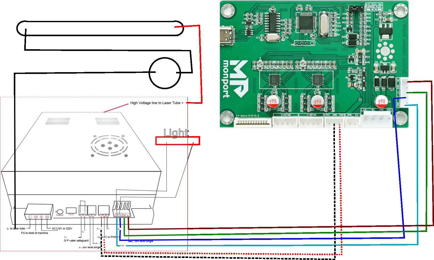
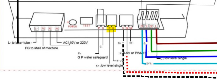
got a picture of wireing (not my best work?
In one of your previous pictures it looked like K+ might have been plugged into something. Also, K- and K+ on the diagram seem to be labeled opposite of what’s on your machine so that’s interesting and something to watch out for. I believe these are commonly connected to a test switch on the control panel.
Is the “Light” that you have showing in the diagram always lit when the machine is on?
As before … this all seems to add up to a failed lps or power supply.
I didn’t find where he stated it was lasing when the IN was disconnected. This has to be the power supply.
30mA from one of these supplies, is pretty high current output for something that is standard with a 30 to 35W tube.
19mA is the more than the maximum of a 40W tube. It also likely you have more like a 30 to 35W tube. If you’re going to test with outrageously high over current, you should just take it out back and bury it.
Keep under the maximum power… especially during testing… Anytime you lase it at over it’s limit, which is everything over 50% the way you’re operating is damaging the tube…
Usually I don’t say anything but you need to back way off this or you won’t have a tube and all this will be moot.
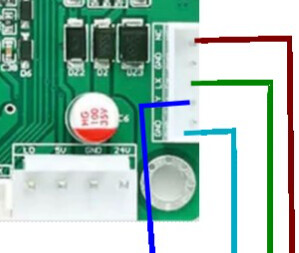
Sorry I picked the wrong port on the pic.
all my wires are blue :o(
(wire in my drawing)
red goes to Lo
green to 5v
blue to gnd
light blue to 24v
K+ & K are reversed, (i used pic. off web)
there is only 1 wire in that plug goes to K+ (i believe goes to the test fire on the digital panel, it was not connected for the test, it will only function if the connector from the digital panel is also connected to GIN5V )
This was my initial thought when first hearing that it fired without PWM.
However, a couple of things bother me about that diagnosis:
the laser worked correctly prior to board swap and modulated power predictably with the digital panel
this doesn’t explain how the machine is firing without PWM
While I think a bad LPS is still possible I suspect there must be something going on with wiring.
@Kenbeckett Can you check if there is a voltage reading on G, IN of LPS with PWM cable disconnected? If you get no reading, can you check while the machine is firing?
This explains it. Basically for some reason there’s always voltage there. Question is why.
I don’t see anything obvious in the wiring that would directly cause this. Perhaps try disconnecting the 24V connector and see if you still have voltage on the G and IN pins.
If yes, then very likely bad LPS. If not, then still likely bad LPS but possibly something else going on.
And to confirm, your laser worked completely normally and predictably prior to the board swap?
This is interesting. Can you check voltage at G and IN with the original board connected? If it’s still 0V then I wonder if the board is still at fault somehow.
No. I think you’re good. I’m fairly certain it’s the board that’s at fault but I can’t say what the fault condition would be that would cause that behavior.
It’s for sure either the board or the LPS but given that behavior seems normal with the original board it’s seems logical that the board is at fault. However, I’m not ruling out the possibility that the LPS is bad and somehow the new board is just making that apparent.