I’m not sure if this is a Lightburn issue or possibly a laser issue, but I’ll post it here either way…
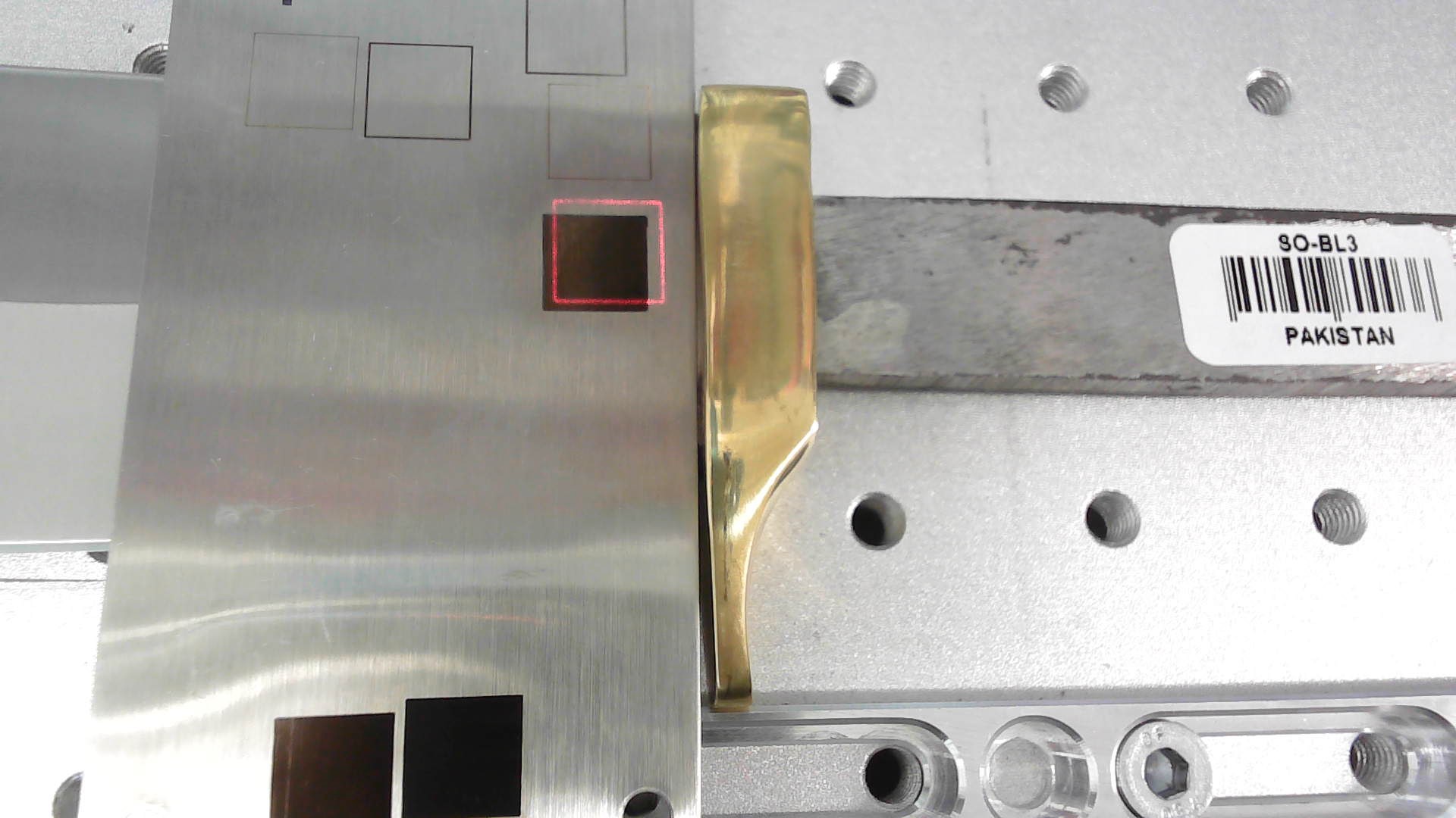
Can someone tell me why this would get out of alignment when ever the focus distance is changed, it never use to do this and I’m at a loss why it started. I had the focus set when this plate was laying on the table and it put the red box perfectly around the engraved square. I raise the plate up off the table maybe 3/8" of an inch and now its not aligned as shown in the picture. Every time I change the focus distance whether I raise or lower the head, I have to re-adjust the X and Y offsets Lightburn to get it lined up again.
I ran the same box test in Ezcad engraving it with the tag on the table focused at 13", then raised the tag up 1" and re-focused to 13", engraved and the red preview is perfectly aligned so in my thinking it something in Lightburn.
Did you import the ezcad setting when you set it up?
I don’t follow what you are doing… I think.
Lightburn can’t tell you moved anything, so how can the software change it?
Are you centered?
![]()
if you raise the object without raising the head they red dot will move. They sources aren’t aligned so the offset corrects for that at the focal plane.
If it’s changing when you raise or lower the head, but you are bringing it back into focus I would probably look at the red dot laser in the laser head and make sure its not loose or something isn’t moving it when you raise and lower the head. It would not take much movement to shift the preview that much.
To show this visually, if your actual laser is the green line, and the red dot pointer is the red line, and they’re not in alignment, you’d have an offset, like this:
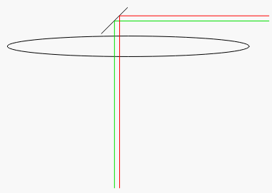
This can happen for a couple different reasons - one, as shown, is that the physical beams are not properly aligned, but the other is that different wavelengths of light refract differently through the lens (or any medium), which is why prisms make rainbows: the different frequencies of light bend at different rates.
So, the red dot light bends a different amount through the lens, and needs to be either shifted, scaled, or both, to account for all of it. That produces beam paths that look more like this image:
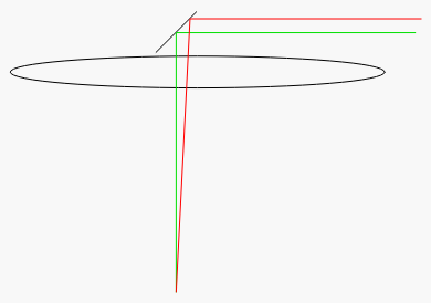
If you physically raise or lower the material (or the lens), you are no longer at the focus point everything is calibrated for, and you are also no longer at the convergence point of those two beams.
This topic was automatically closed 30 days after the last reply. New replies are no longer allowed.