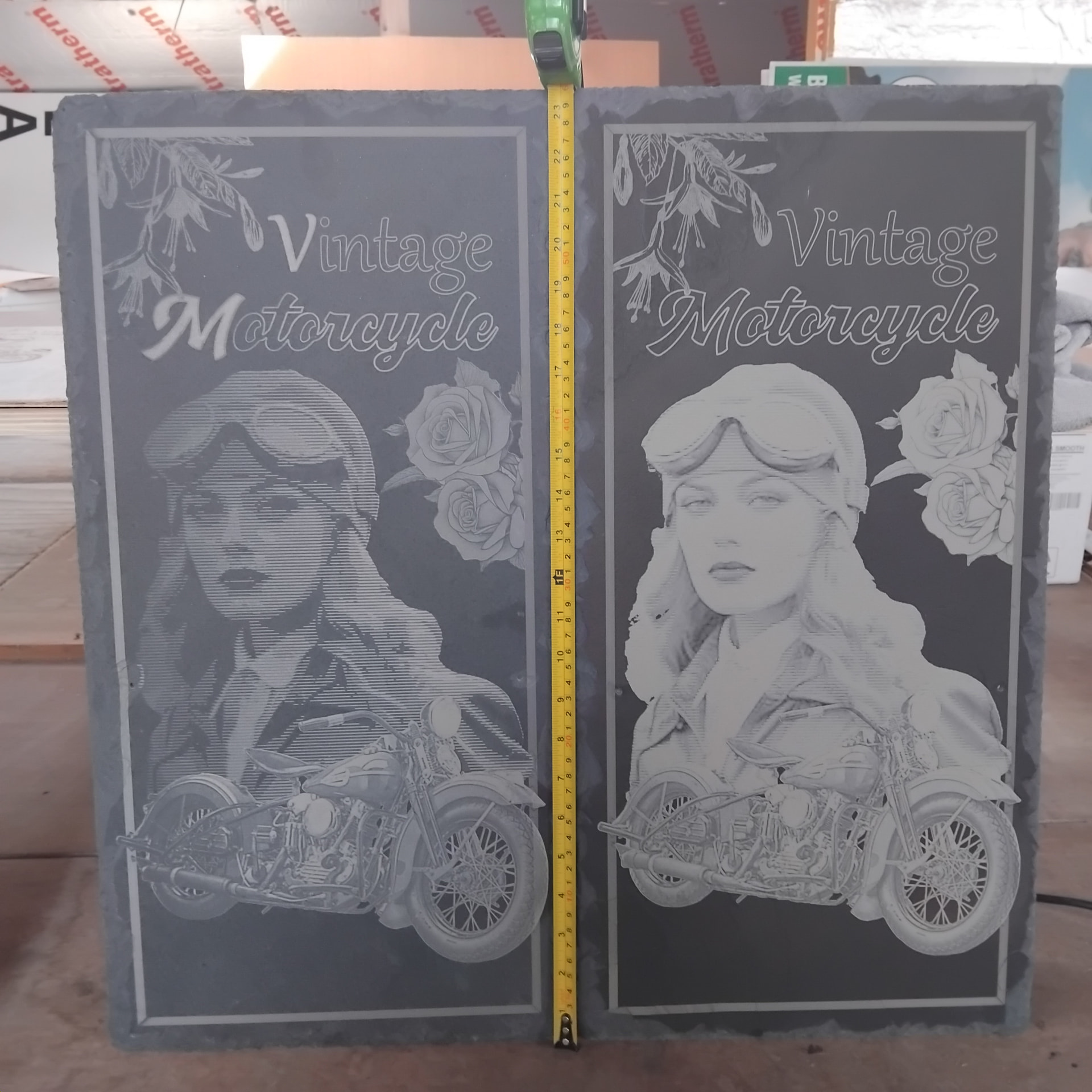
I was looking at an image in preview yesterday and it caught my attention that the image was darker than I had seen it previously in preview. I have been trying to think it through and thought maybe I changed power % and it’s showing the image darker because of that, but then I remembered I had perhaps previously viewed the image in Greyscale and then changed to Stuki, and got a different view.
Oh Crumbs, I had the image inverted…while simultaneously trying to balance the bright and darker tones in a vintage motorbike headlight, without crushing the tones at the rear end of the bike and using the Preview as a calibration tool.
Don’t use preview to judge whether the image is going to look correct on the material. The only thing preview is for is to show you where the laser will move, and where it will fire. It was never intended to show more than that.
The lines in the preview are a constant width on screen, which isn’t how the output from the laser works in the real world.
Is there any direct relationship between the tones used in the preview or the image adjustments window and the output power values at the diode module.
Sudden thought! Can the module power output values (#values) be found in the gcode.
The actual effect on the material is a separate concern at this point.
I’m trying to find a way to carry out what’s called ‘matching histograms’ in the photo image processing software ‘DarkTherapee’, before transferring the image to LB. I’m thinking that is what LB does with ‘Material library’.
The effect on the material will be captured from a LB material test and the Raw data sample will be used to calibrate the the first histogram (from the original image).
In grayscale image mode, yes, though the numbers from the image go through a gamma correction table to linearize them, then have whatever brightness, contrast, and gamma you apply put back on them first. In any of the dither modes the only output power values are 0 and the Max Power value you specify.