I’ve watched the video and things are somewhat clearer but not entirely clear.
I’m assuming it’s the top and bottom dots on the material that you are aiming at when you do the target position alignment. Correct me if this is not the case.
What in the mandala design are you using as the reference points for those targets? I don’t see anything in the .lbrn project other than the mandala design itself.
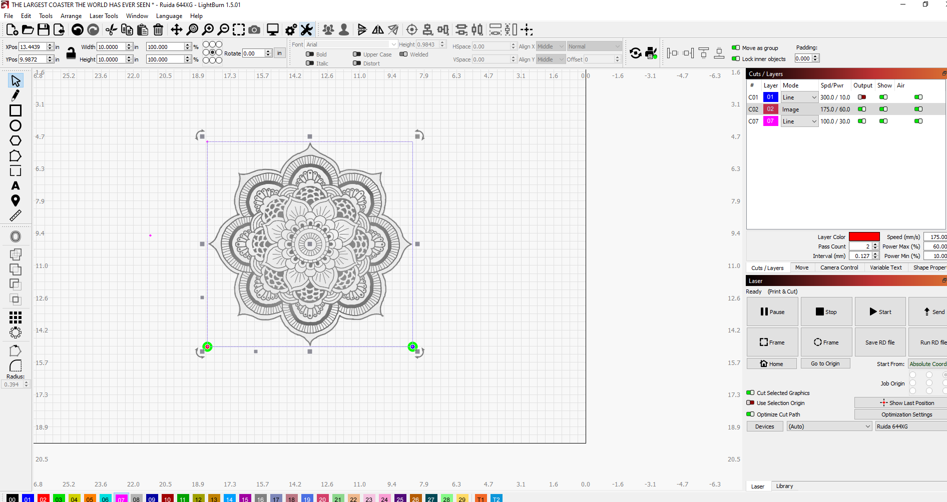
there is a blue square that matches the natural red square surrounding the border of the mandala . both are 10x10"… you have the file, what dont you see? Why are you “assuming” the top and bottom dots are what Im aiming for? 1. the image shows this. 2 the video shows this. 3. logic alone shows this. The problem exists going left to right, not up and down.
What are you referring to here? I see nothing like this in the lbrn file.
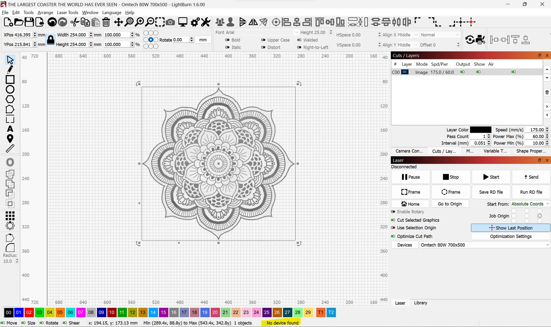
This is what I see. Note that I’ve selected all here and only one object is selected. Is there something else that’s supposed to be here?
You state so in the video. The two dots that you marked on the material. Is that not what you are using for alignment?
However, I can see now that the .lbrn file doesn’t match the screenshots.
Update on this. I can now reproduce the effect that you’re getting. However, it’s not clear to me what’s going on. I’ll try to investigate this a bit more tomorrow.
What version of LightBurn are you using?
are you even a Lightburn technician or a guy just hanging out in the forums? If you are a Lightburn tech, then who’s your supervisor, because this analysis is ridiculous! Why havent you been able to begin any technical commentary on this yet?
I watched the video and had a look at the images and my first thought is that your X axis is out of calibration.
Have you tried rotating the job 90 degrees and see if the error moves onto the Y axis?
will try that, because I contacted Omtech the other day about my Y axis grinding… finally something technical sounding that moves forward…
To the OP: why are you talking crap to a very knowledgeable person trying to help you. Be grateful.
no… he slows me down. dealt with him before.
repositioned the P&C markers to lower portion of design. Things got worse. If we call the lower left marker #1, the lower right #2 , the upper right corner #3, and the upper left corner #4 (basically going counterclockwise), then we get these results:
start at position #2, the the laser goes up to position #3 but overshoots it high by about 1.25", then heads left to position #4 (still high above at 1.25") and drops down alongside position #4 but wide about 1/8" to its’ left, then heads down to position #1 (still wide about 1/8"), then heads back to position #2 but lower by about an 1/8". Like totally not square at all, and totally not 10x10". Is calibration the issue, or is my Y axis motor making things a problem, because that motor is grinding?
I’m perfectly happy to disengage by request. You needn’t make a fuss. Best of luck.
If you suspect you may have a problem with your machine, you have to fix that before you can even begin to start troubleshooting your job file or the software.
If the problem was just the calibration rotating the points 90 degrees wouldn’t cause the the problem to shift to to the Y axis and the scale of the error wouldn’t change.
sent the info to Omtech… maybe they can help find a solution… only happens in P&C
This topic was automatically closed 30 days after the last reply. New replies are no longer allowed.