Good afternoon
I’m just starting to work with lightburn, and at the moment I have a problem with the camera. I use an Acer ACR010 camera, with an OV5648 module, a viewing angle of 70 degrees and a fisheye effect. I fixed the camera in height so that my working field of 1505x1255 mm fits. Through the camera program in Windows, the image for calibration is quite clear and you can make out everything, but lightburn cannot find the image. Maybe the problem is in the lighting, glare or the height of the suspension? Has anyone had a similar problem and can anyone help?
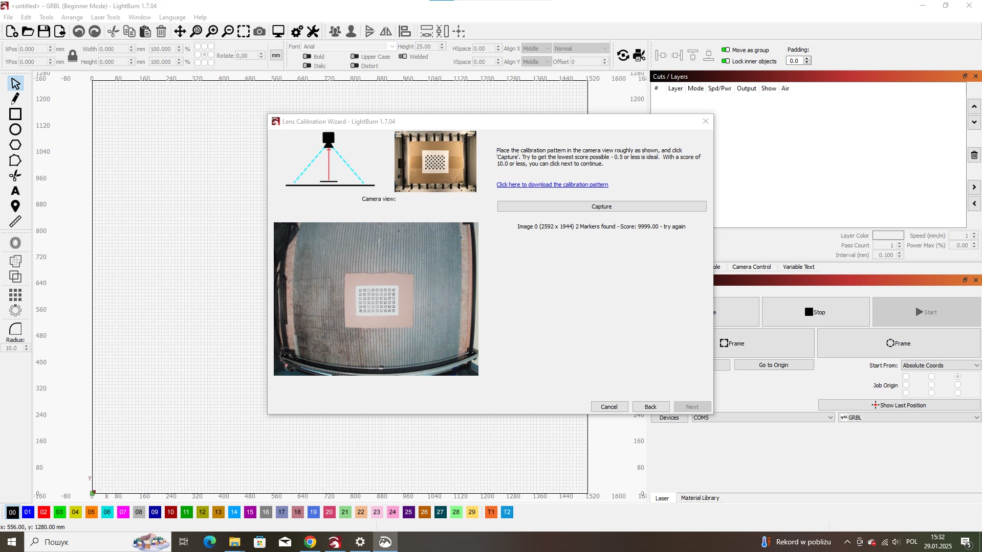

Try to get the second test pattern to work, the one with the black circles. I’ve never been able to get the “new” ones to work either.
Hi


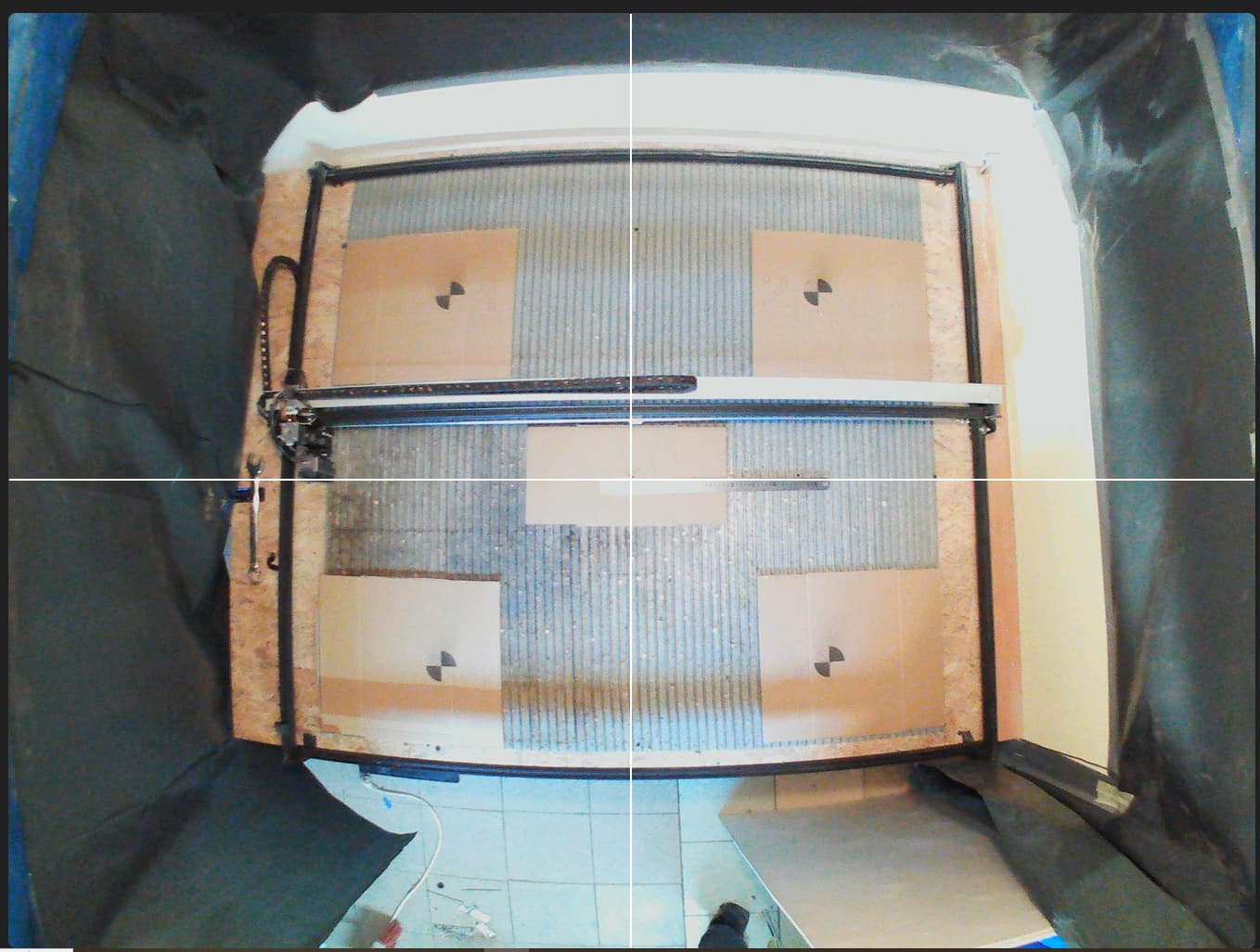
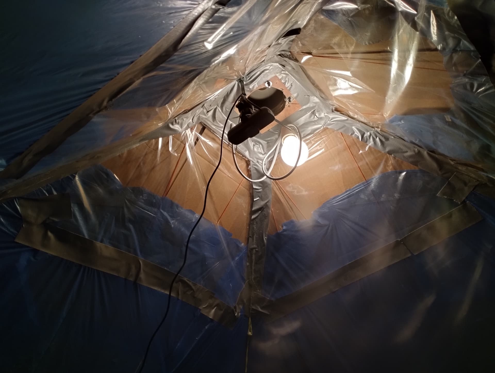
I used the old pattern and with problems but passed the camera lens calibration. I moved on to the camera alignment calibration and then other problems started. I experimented for a long time with the angle of inclination and the height of the camera suspension, but I constantly have a shift of the actual image compared to what I see in the camera. As you can see in the photo, the image is almost superimposed on the edges, but in the center it runs off by about 1 cm in different directions. Also, in my standard Windows camera program, I can see image distortion, is this a camera defect or maybe I need to adjust something?


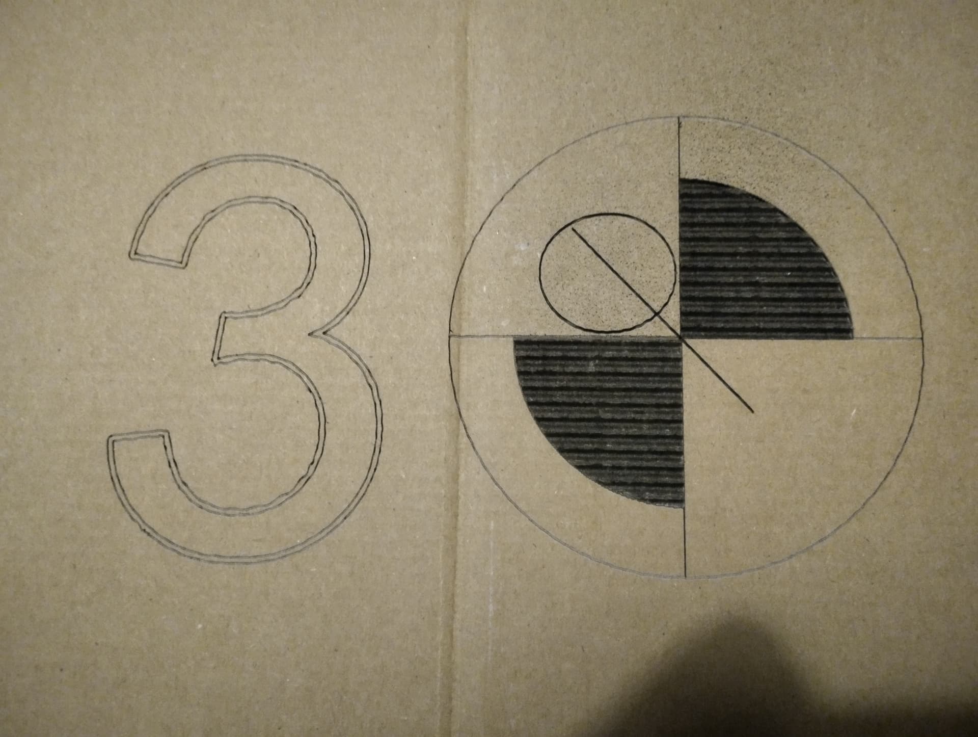
Did you “print” the 4 number tags individually, or did you print them after you positioned the plates in one go?
In addition to your camera problem, you also have a mechanical problem with your gantry. The print image looks a bit rough.
my cardboard is too small lightburn still sees the honeycomb, put sheets of white A4 paper over the entire surface and watch your lighting.
all labels are printed on a laser at once, the scale is 500% - maximum possible in program in my case
what exactly is the mechanical problem with the portal? I used ordinary cardboard from used boxes, maybe you need to choose the parameters of speed, power and focal length more carefully - does this have a strong impact on calibration?
my working field is 1505x1255 mm - you need a lot of leaves ![]() honeycombs do not interfere with niap lens calibration, I passed, the problem is with alignment. As for the lighting, I used a 50-watt LED spotlight, but it caused strong light on the paper and it was not possible to pass the calibration, so I switched to a regular light bulb.
honeycombs do not interfere with niap lens calibration, I passed, the problem is with alignment. As for the lighting, I used a 50-watt LED spotlight, but it caused strong light on the paper and it was not possible to pass the calibration, so I switched to a regular light bulb.
1 Like
try with the other pattern for the sight, there is one with circles
ok, I was a little afraid that you brought in the 4 targets from outside and just arranged them as you please ;-).
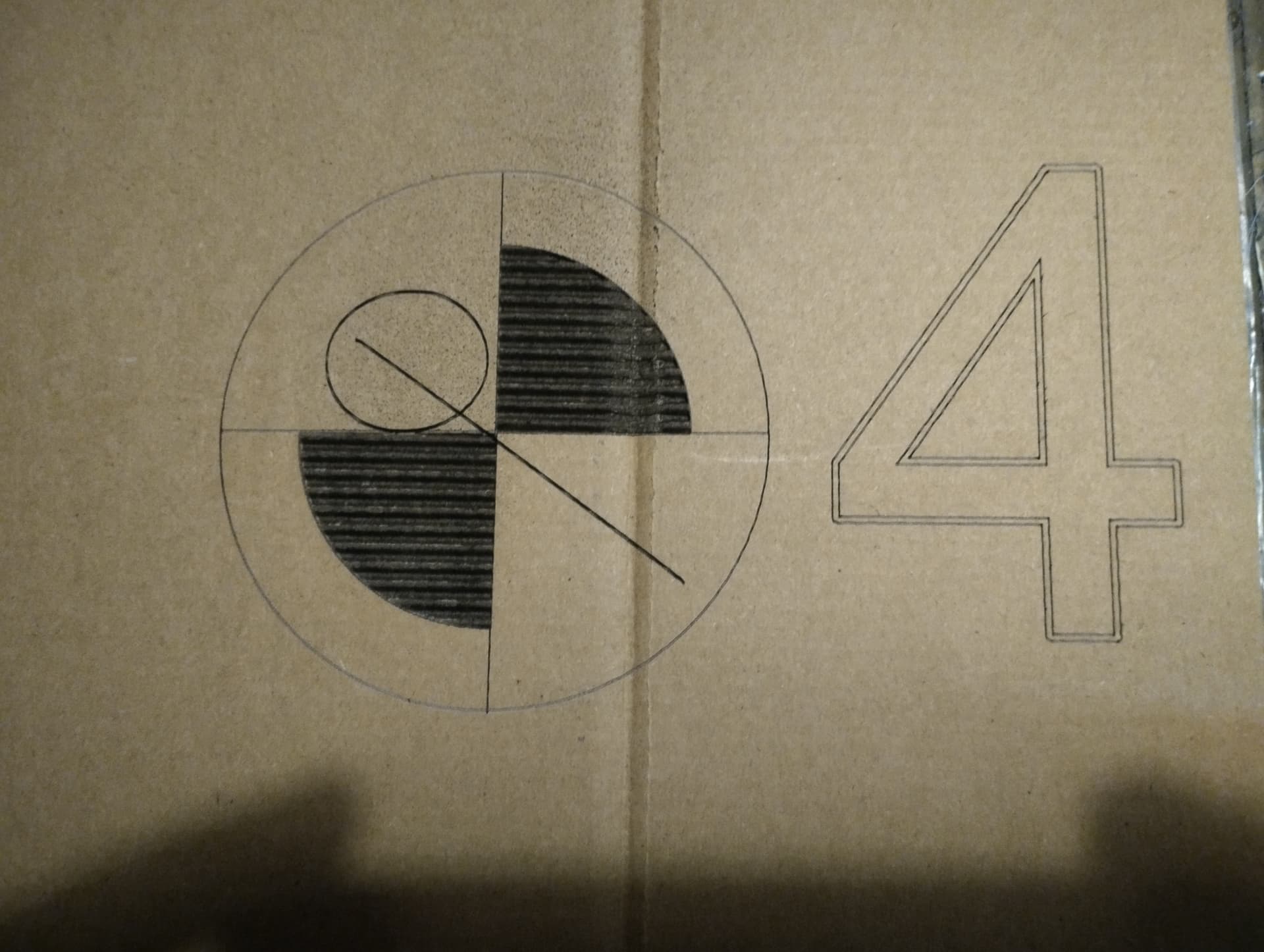
If you zoom in on target no. 3 you can clearly see that there is something that needs to be fine-tuned, the jagged lines in the number should not look like that. It could be your timing belt that is too loose or too tight, or one of the small pinion screws is loose in one of your pulleys.
try to put the camera in the center and levels, after possible that the problem comes from the fact that your surface is rectangular
No, I did everything according to the instructions in the program, but regardless of the camera location, either the center or the edges were shifted. I think the problem is in the camera, look at the picture, the black screws mark the edges and middle of the workspace, the vertical line passes through the center but is shifted at the edges.
You are right, the belt on the left motor was loose, and I used a y-axis motor synchronizer made of two aluminum rods connected by a flexible coupling, this added vibrations to the y-axis, but I will solve this problem. Nevertheless, the problem with the camera remains. In my area it is difficult to find good quality plywood, but what I have is quite torn and I want to fix it with screws, but I am afraid that with such a camera offset I will screw the screw into the workpiece and not the free space.
I placed the camera perfectly in the center of the workspace, for centering I use the construction method - a string with a load on the end, the camera was directly above the center with an accuracy of 5 mm. I didn’t take a photo, but then my center coincided almost perfectly, but all the edges were leaking. By trial and error, I moved the camera to three sides and achieved the result as shown in the photo. Three corners except number 4 are almost perfect, but the center is displaced. I used the data from the program for the height of the camera suspension, but I can lower it much lower and still keep the image of the full desktop due to the fisheye effect. I already suspect that the problem is in the camera, or rather in the lens or some kind of defect, the camera module has the same designation as those sold by Lightburn, but the price is 10 times lower. Look at the photo, when centering vertically, my edges are leaking to the sides, focus on the black screws screwed into the desktop.
My english is very bad, so I must use google translate, sorry for this/
1 Like
I used this table
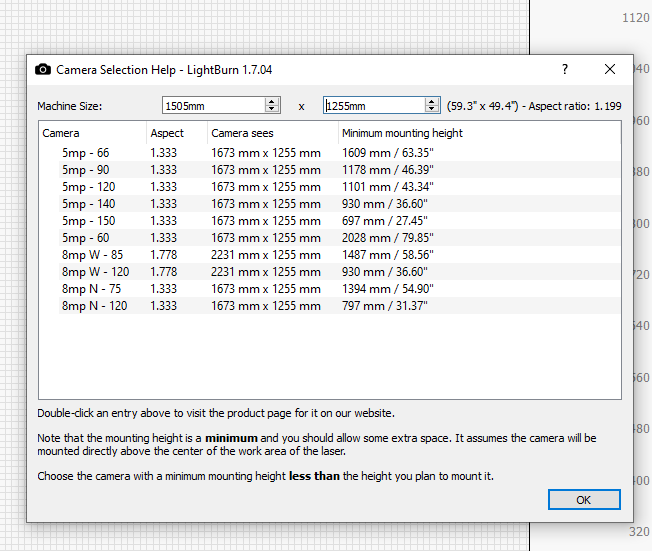
to determine the height of the camera. According to the passport data, the camera’s viewing angle is 70 degrees, I was guided by 66 degrees from the plate and hung it at a height of 1.6 meters. But due to the fisheye effect, I can capture the entire working surface at a height of about 1 meter. I don’t know if I should be guided by the data from the plate, or maybe they are only applicable to lightburn cameras, or maybe it is worth lowering the camera lower and getting a more detailed image?
To me it looks like your lens is not calibrated yet, image should be “flat” after a successful calibration.
If your distance to the material surface and camera position is static and doesn’t move at all, you should also get a sub-millimeter accuracy. But as I said, it’s step 2 and you’re “missing” the first step, in my opinion.
You could also try the new version of LB 2.0, they have improved the camera section, but I haven’t been able to test that yet.
1 Like